Thin-film batteries with soft and hard electrolyte layers and method

a technology of electrolyte layer and thin film, applied in the direction of non-aqueous electrolyte cells, cell components, sustainable manufacturing/processing, etc., can solve the problem of randomly spaced pinholes/defects, and achieve the effect of improving the environmental resistance to water vapor and oxygen

Inactive Publication Date: 2007-01-18
CYMBET CORP
View PDF99 Cites 124 Cited by
  • Summary
  • Abstract
  • Description
  • Claims
  • Application Information

AI Technical Summary

Benefits of technology

[0013] In some embodiments, the present invention includes a battery having an electrolyte structure that combines a plurality of layers of different electrolytes (e.g., hard-soft-hard). In some embodiments, a thin (0.1 to 1.0 micron) LiPON electrolyte layer serves as a hard coating on the negative electrode preventing the formation of lithium dendrites (especially when paired with a corresponding LiPON electrolyte layer coating on the positive electrode) and / or providing an even (smooth), hard layer of lithium metal on, or as part of, the negative electrode when the battery is charged. In some embodiments, a thin (0.1 to 1.0 micron) LiPON electrolyte on only one electrode (e.g., the negative electrode) may not prevent the formation of lithium dendrites over the long term (e.g., many thousands of discharge-recharge cycles), since the lithium growing through a pinhole may only need to grow about 3 microns or less across the electrolyte to short the battery (i.e., providing a metal electrical conduction path directly from anode to cathode). When LiPON is also used as a coating at the positive electrode (e.g., an electrode that includes LiCoO2) the random locations of the pinholes will not line up (e.g., across the electrolyte from anode to cathode) so lithium would also need to grow sideways in the electrolyte, which doubly ensures that lithium plating at a defect site (which would typically form a dendrite) will not short the battery. In some embodiments, a soft electrolyte layer bridges the gap between the hard electrolyte layer on the negative electrode and the hard electrolyte layer on the positive electrode. At both electrodes, the LiPON layer also provides an improvement in environmental resistance to water vapor and oxygen, especially during manufacture before the battery is completed and otherwise sealed. In some embodiments, the soft electrolyte includes a solid polymer electrolyte (SPE) layer that is located between and contacts with the LiPON layer on the positive electrode and the LiPON layer on the negative electrode. In some embodiments, the electrolyte structure includes a polymer electrolyte such as PEO-LiX (poly-ethylene oxide lithium-X, where LiX=a metal salt, such as LiPF6, LiBF4, LiCF3SO4, CF3SO3Li (lithium trifluoromethanesulfonate, also called triflate), lithium bisperfluoroethanesulfonimide, lithium(Bis)Trifluoromethanesulfonimide, and / or the like, for example). In some embodiments, the electrolyte structure includes a polymer electrolyte such as polyPN-LiX (Polyphosphazene with lithium-X, where LiX=LiPF6, LiBF4, LiCF3SO4, and / or the like, for example). In some embodiments, a small-molecule additive, such as propylene carbonate, that influences the ionic conductivity and physical properties of the polymer electrolytes is added to form a gel electrolyte that better fills defects and acts as an adhesive.

Problems solved by technology

In some embodiments, a thin (0.1 to 1.0 micron) LiPON electrolyte on only one electrode (e.g., the negative electrode) may not prevent the formation of lithium dendrites over the long term (e.g., many thousands of discharge-recharge cycles), since the lithium growing through a pinhole may only need to grow about 3 microns or less across the electrolyte to short the battery (i.e., providing a metal electrical conduction path directly from anode to cathode).
In some embodiments, a hard glass-like electrolyte layer obtains a smooth hard positive-electrode lithium-metal layer upon charging, but when such a layer is made very thin, will tend to have randomly spaced pinholes / defects.

Method used


Image

  • Thin-film batteries with soft and hard electrolyte layers and method
  • Thin-film batteries with soft and hard electrolyte layers and method
  • Thin-film batteries with soft and hard electrolyte layers and method

Examples


Embodiment Construction

[0035] Although the following detailed description contains many specifics for the purpose of illustration, a person of ordinary skill in the art will appreciate that many variations and alterations to the following details are within the scope of the invention. Accordingly, the following preferred embodiments of the invention are set forth without any loss of generality to, and without imposing limitations upon the claimed invention.

[0036] In the following detailed description of the preferred embodiments, reference is made to the accompanying drawings that form a part hereof, and in which are shown by way of illustration specific embodiments in which the invention may be practiced. It is understood that other embodiments may be utilized and structural changes may be made without departing from the scope of the present invention.

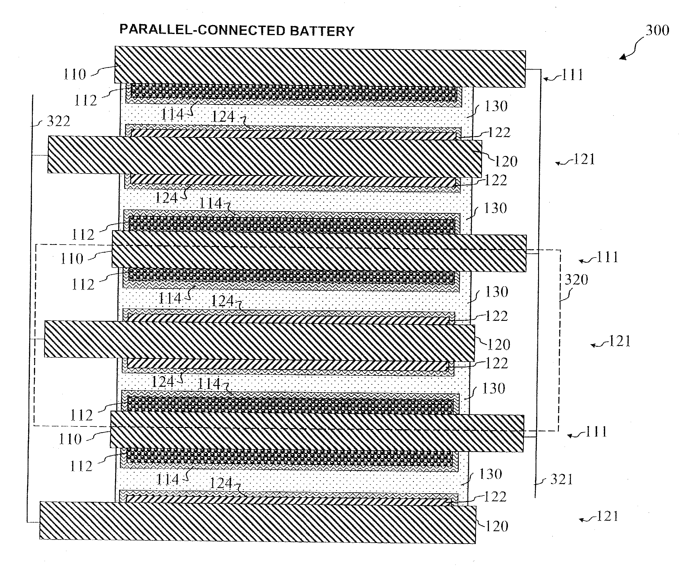
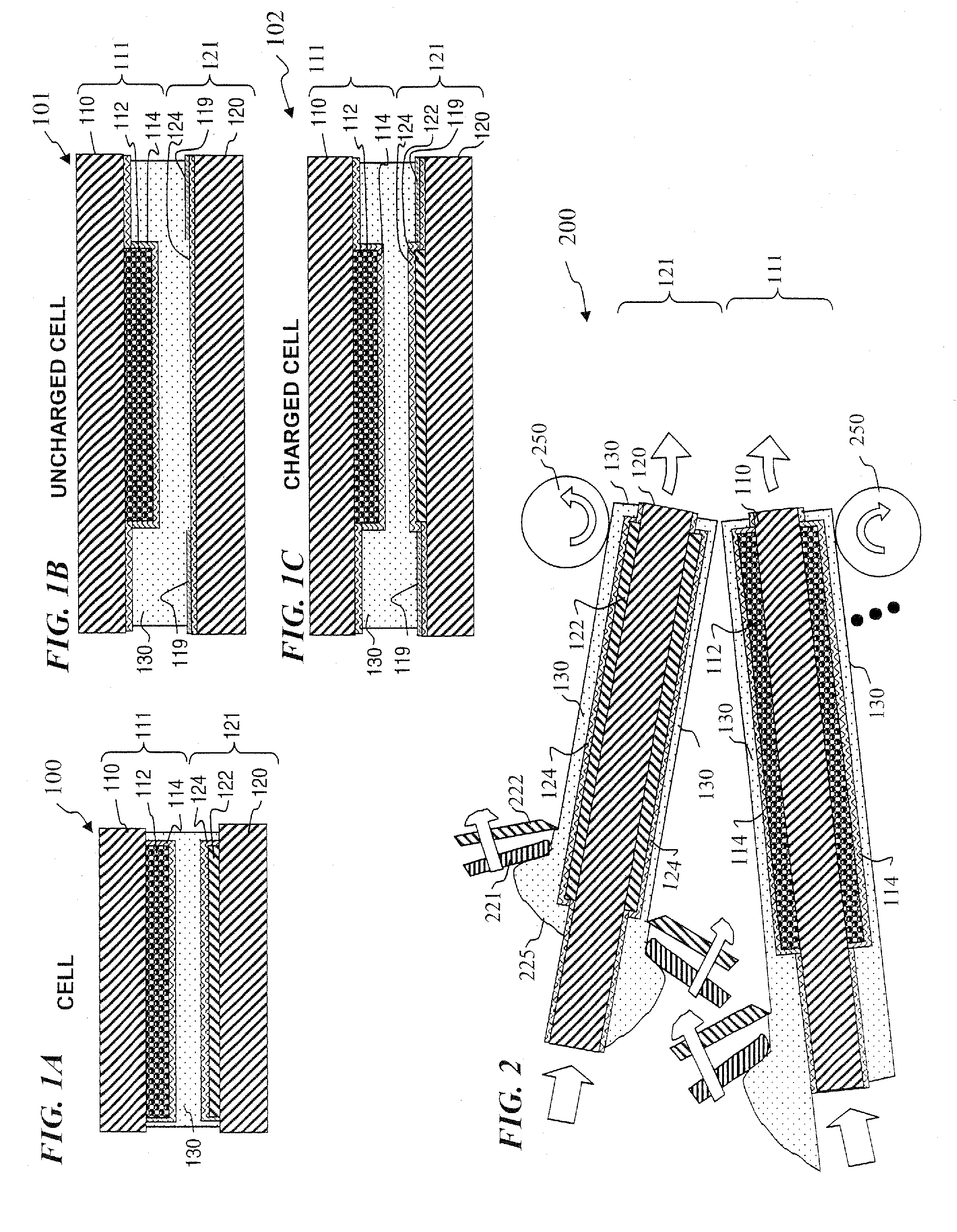
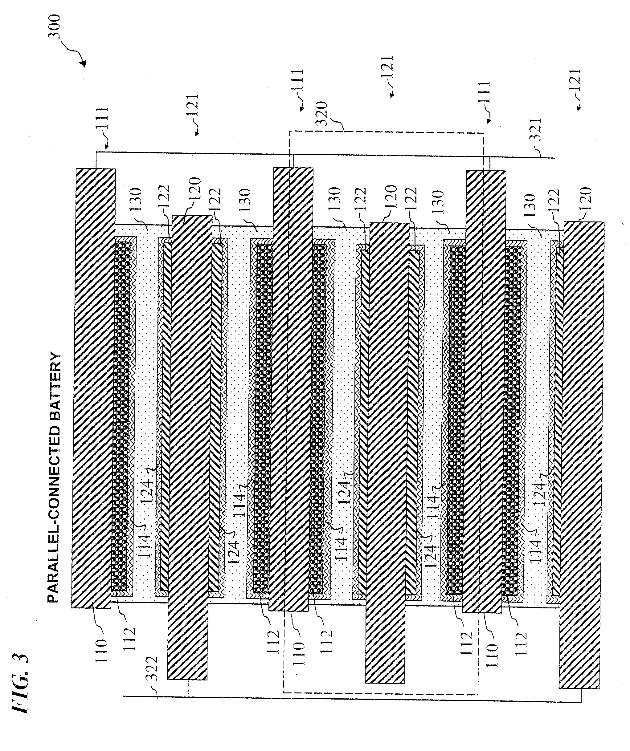
[0037] The leading digit(s) of reference numbers appearing in the Figures generally correspond to the Figure number in which that component is first intr...


PUM

PropertyMeasurementUnit
ion conductivityaaaaaaaaaa
thicknessaaaaaaaaaa
thicknessaaaaaaaaaa

Abstract

A method and apparatus for making thin-film batteries having composite multi-layered electrolytes with soft electrolyte between hard electrolyte covering the negative and/or positive electrode, and the resulting batteries. In some embodiments, foil-core cathode sheets each having a cathode material (e.g., LiCoO2) covered by a hard electrolyte on both sides, and foil-core anode sheets having an anode material (e.g., lithium metal) covered by a hard electrolyte on both sides, are laminated using a soft (e.g., polymer gel) electrolyte sandwiched between alternating cathode and anode sheets. A hard glass-like electrolyte layer obtains a smooth hard positive-electrode lithium-metal layer upon charging, but when very thin, have randomly spaced pinholes/defects. When the hard layers are formed on both the positive and negative electrodes, one electrode's dendrite-short-causing defects on are not aligned with the other electrode's defects. The soft electrolyte layer both conducts ions across the gap between hard electrolyte layers and fills pinholes.

Description

CROSS-REFERENCE TO RELATED APPLICATIONS [0001] This invention claims benefit of U.S. Provisional Patent Application 60 / 699,895 filed Jul. 15, 2005, which is hereby incorporated by reference in its entirety. This is also related to U.S. patent application Ser. No. 10 / 895,445 entitled “LITHIUM / AIR BATTERIES WITH LiPON AS SEPARATOR AND PROTECTIVE BARRIER AND METHOD” filed Oct. 16, 2003 by J. Klaassen, the inventor of the present application, and to U.S. patent application Ser. No. 11 / 031,217 entitled “LAYERED BARRIER STRUCTURE HAVING ONE OR MORE DEFINABLE LAYERS AND METHOD” filed Jan. 6, 2005, U.S. patent application Ser. No. 11 / xxx,xxx entitled “THIN-FILM BATTERIES WITH POLYMER AND LiPON ELECTROLYTE LAYERS AND METHOD” (Attorney docket number 1327.031us2) and U.S. patent application Ser. No. 11 / xxx,xxx entitled “APPARATUS AND METHOD FOR MAKING THIN-FILM BATTERIES WITH SOFT AND HARD ELECTROLYTE LAYERS” (Attorney docket number 1327.031us3), filed on even date herewith, which are all inco...

Claims


Application Information

Patent Timeline
Patent Type & Authority Applications(United States)
IPC IPC(8): H01M10/40H01M10/04H01M4/52H01M4/525H01M10/052H01M10/056H01M10/0562H01M10/0565H01M10/058H01M10/36
CPCH01B1/122Y10T29/49115H01M4/382H01M4/525H01M6/185H01M6/187H01M10/052H01M10/056H01M10/0562H01M10/0565H01M10/058H01M2300/0068H01M2300/0085H01M2300/0094Y02E60/122H01M2/0202Y02E60/10Y02P70/50H01M10/36H01M10/05
Inventor KLAASSEN, JODY J.
Owner CYMBET CORP
Why Eureka
Try Eureka