Monitoring device for flexible heating elements

a monitoring device and flexible technology, applied in the direction of ohmic-resistance heating, heating element shapes, electrical appliances, etc., can solve the problems of inadmissible heating of heating elements, damage to heating conductors and contact conductors, and local damage to heating elements, so as to avoid damage through overheating and avoid overheating

Inactive Publication Date: 2006-06-27
I G BAUERHIN GMBH
View PDF11 Cites 4 Cited by
  • Summary
  • Abstract
  • Description
  • Claims
  • Application Information

AI Technical Summary

Benefits of technology

[0008]In accordance with the invention, the objective is achieved by providing a controlling and monitoring device for avoiding damage through overheating in the case of flexible, textile surface heating elements which consist of at least two opposed contact conductors made of electrically conducting, non-insulated fibers or wires between which there extends a plurality of heating conductors which are electrically connected to the contact conductors, wherein an additional conductor is placed over the heating conductors and connected to an evaluation unit that cooperates with a current-voltage source for the heating conductors in order to avoid overheating.
[0012]In a preferred embodiment, the contact conductors comprise multiple strands of metallic wire and the heating conductors comprise wave-shaped carbon fibers which contact one another at spaced contact points. These characteristics permit the safe operation of heating elements with metallic contact conductors and inter-connected heating conductors consisting of carbon fiber. As these generate high temperatures in the case of defective regions at the contact strip, the high melting temperature of the carbon fiber can lead to considerable damage.
[0013]In the preferred embodiment, the additional conductor includes a filament made of steel. This ensures that it is able to withstand the mechanical bending and upsetting loads and is not destroyed in the region of the contact conductor. In accordance with the invention, this is achieved by a steel conductor which has only moderate conducting characteristics, but which features an excellent mechanical stability.
[0015]In an alternative embodiment, the additional conductor extends in the form of a wave or it may consist of a textile thread enveloped by one or more electrically conductive metal strips, with insulation over the metal strips. These arrangements tend to prevent the additional conductor from being destroyed as a result of mechanical loads.

Problems solved by technology

Because of chemical and mechanical influences such as water, salt and movement on the seats, both the heating conductors and the contact conductors are attacked and locally destroyed in the course of time.
If part of the contact conductors are destroyed, a transition resistance occurs which generates heat along the heating strips which may lead to impermissible heating of the heating element.
This arrangement reduces the problem of overheating, but does not eliminate it.
To prevent corrosive attacks on metallic conductors, there are known surface coatings made of silver and tin, but they can be destroyed by electro-corrosion if salt and moisture are present in the presence of an electric voltage.
The installation of temperature sensors can not prevent the thermal problems affecting the contact conductors.

Method used


Image

  • Monitoring device for flexible heating elements
  • Monitoring device for flexible heating elements
  • Monitoring device for flexible heating elements

Examples


Embodiment Construction

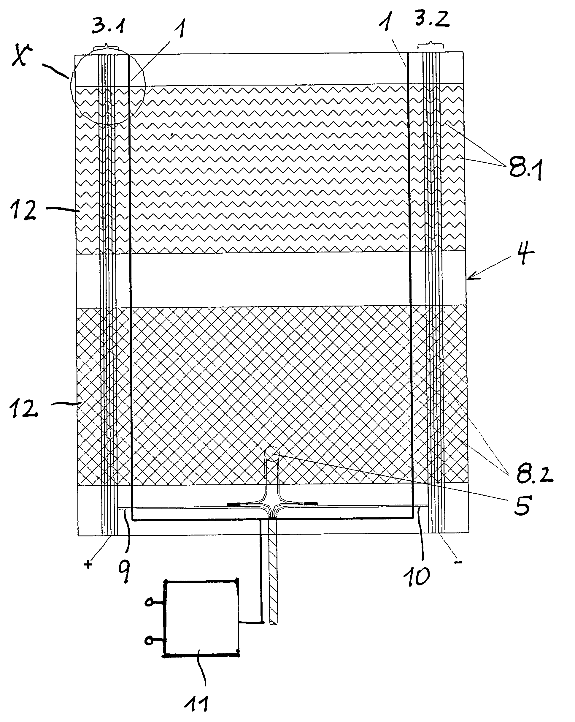
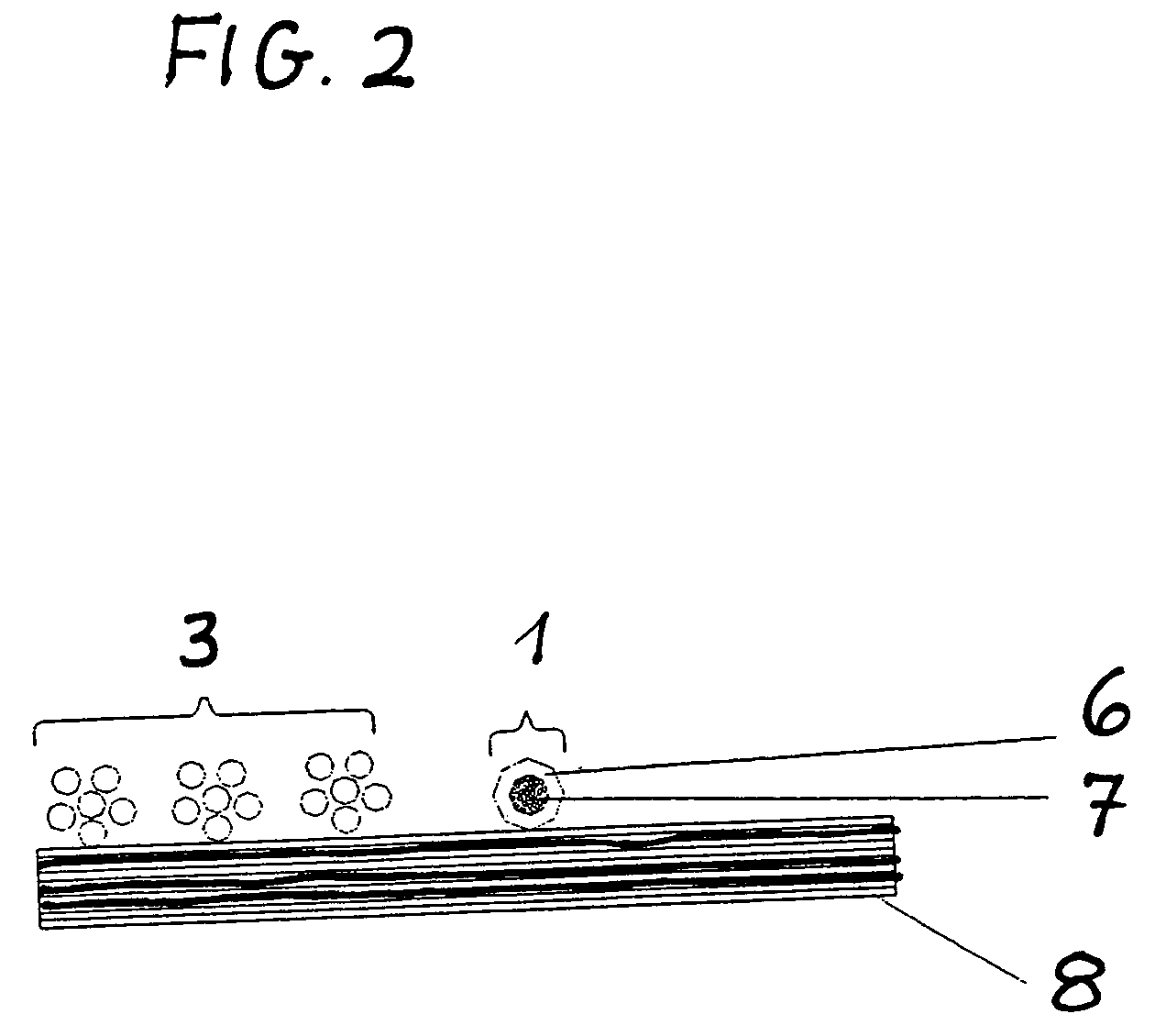
[0019]The heating element according to FIG. 1 consists of a two-part textile surface heating element 4 whose upper part comprises a heating conductor extending in a wave-like way and whose lower part comprises heating conductors arranged in a net-like way.

[0020]At both side edges of the flexible heating element there is provided a region of contact conductors 3.1, 3.2 which, via suitable supply lines 9, 10, are connected to a voltage source (not illustrated).

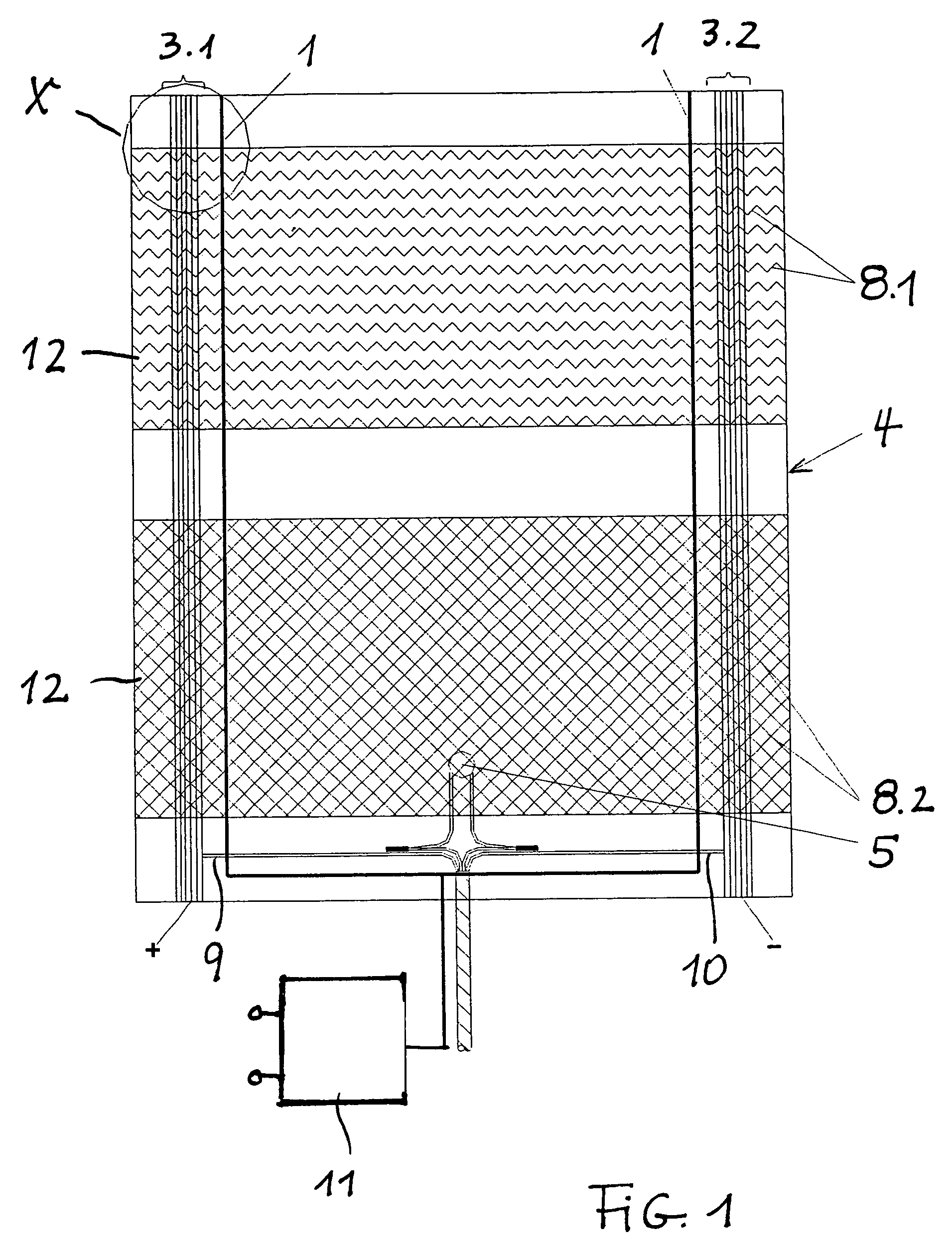
[0021]In parallel to the contact conductors 3.1,3.2 in the inner region of the heating element, there is arranged one additional conductor 1 each functioning as a detection conductor. In the lower region of the heating element, approximately at the level of the supply lines 9, 10, the detection conductors come together and are connected to the evaluation unit 11.

[0022]In the present embodiment, the heating conductors 8.1, 8.2 are provided in the form of carbon heating conductors and the additional conductors 1 in the form of det...


PUM


Abstract

The invention concerns a controlling and monitoring device for avoiding damage through overheating in the case of flexible, textile surface heating elements which include at least two opposed contact conductors (3.1, 3.2) made of electrically conducting, non-insulated fibers or wires between which there extends a plurality of heating conductors (8) which are electrically connected to the contact conductors (3.1, 3.2) and to a current-voltage source. At least one additional conductor (1) is guided along at least one contact conductor over the heating conductors (8), wherein the additional conductor (1) is electrically insulated by a covering material and is connected to an electric or electronic evaluation switch (11). The coating material has a softening range which is above the standard heating temperature of the surface heating element, but below the permissible thermal limit temperature of the surrounding materials and of the base material (12), wherein, in the case of overheating, the coating material melts and wherein the heating conductors (8.1, 8.2), together with the additional conductor, form an electrical contact via which, for the purpose of controlling any overheating, an electric current flows to the electric or electronic evaluation unit which is connected to the current-voltage source.

Description

[0001]The present invention relates to a controlling and monitoring device for avoiding overheating in the case of flexible, textile surface heating elements which consist of at least two opposed contact conductors made from electrically conductive, non-insulated fibers or wires between which there extends a plurality of heating conductors which are electrically connected to the contact conductors.BACKGROUND[0002]DE 4 101 290 and DE 19 831 574 describe textile surface heating elements having at least two opposed strips made of electrically conductive, non-insulated fibers or wires between which there extends a plurality of non-insulated heating conductors consisting of an electric resistance material.[0003]This type of heating element is primarily used for heating seats in motor vehicles. Because of chemical and mechanical influences such as water, salt and movement on the seats, both the heating conductors and the contact conductors are attacked and locally destroyed in the course ...

Claims


Application Information

Patent Timeline
Patent Type & Authority Patents(United States)
IPC IPC(8): H05B3/34
CPCH05B3/342H05B2203/003H05B2203/005H05B2203/029H05B2203/011H05B2203/014H05B2203/017H05B2203/007
Inventor MICHELMANN, JOCHEN
Owner I G BAUERHIN GMBH
Why Eureka
Try Eureka