

Robotic modeling of voids
- Summary
- Abstract
- Description
- Claims
- Application Information
AI Technical Summary
Benefits of technology
Problems solved by technology
Method used
Image

Examples
first embodiment
[0079]To aid in comprehension, an adaptable robot for mapping the interior structures of a mine will be described, but these concepts are easily adaptable to other voids, such as tunnels, pipes, caves and wells, all within the scope of the present invention. Further, the device orientation and feature selection described below should be considered exemplary and optional, respectively, and should not be used to limit the scope of the present invention in any way. One skilled in the art, for example, could easily adapt the rugged mine robot in the first embodiment to one for mapping caves or tunnels which may be at least partially filled with a noxious liquid.
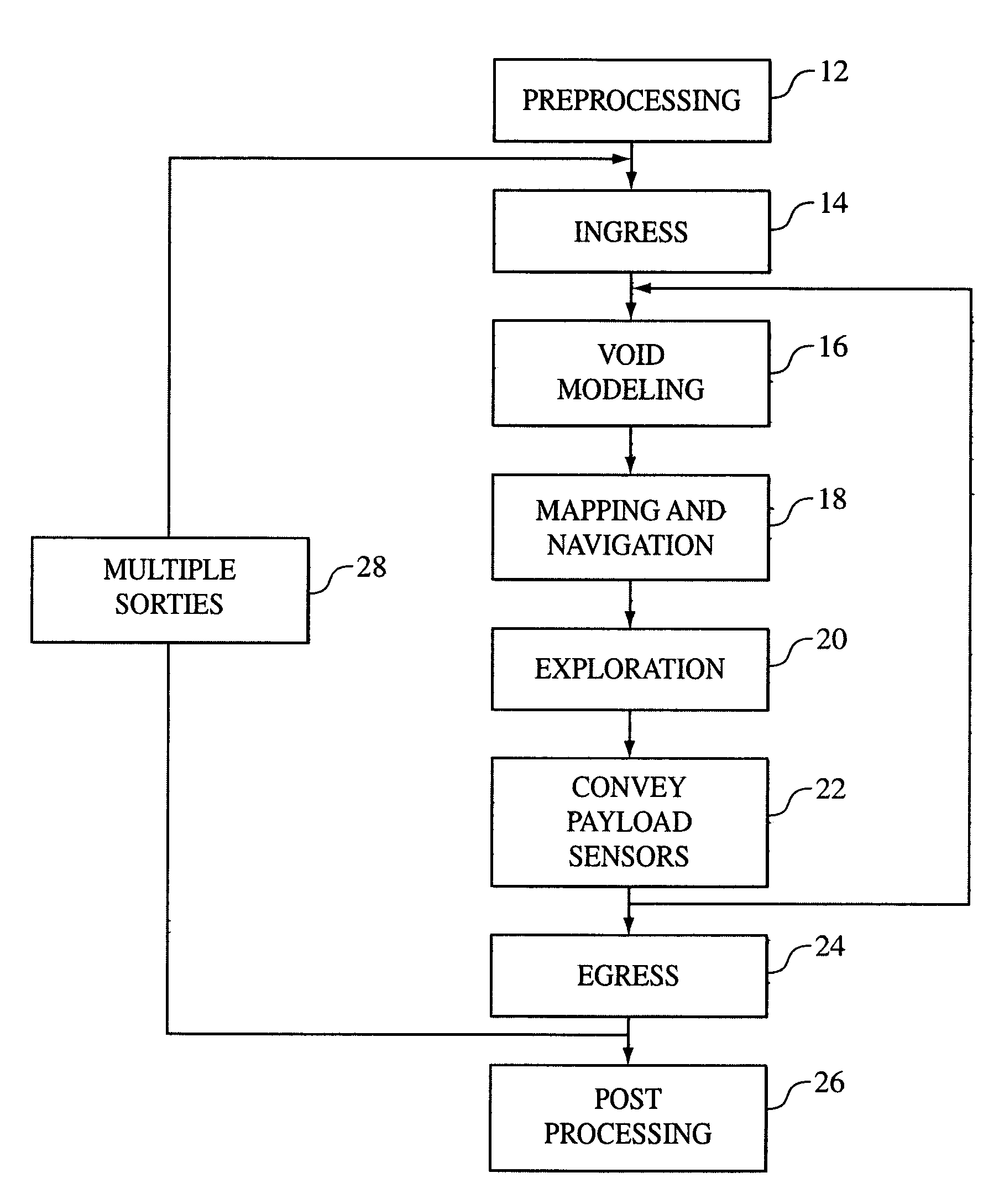
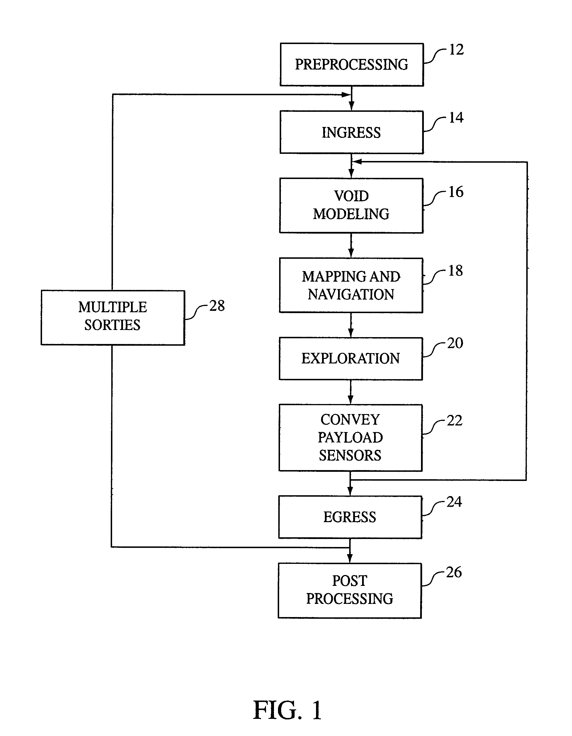
[0080]Looking back at FIG. 1, it is shown that the overall robotic void modeling process initiates with a preprocessing step 12. For the exemplary embodiment of robotically mapping a region of a subterranean mine, pre-processing includes analyzing the pre-existing information abut the mine and surrounding areas in order to genera...
embodiment 340
[0094]FIGS. 13C and 13D detail an additional swimming embodiment 340 utilizing multiple thrusters 344 that control all axes of position, orientation and motion without the need for longitudinal velocity. Because this robot utilizes momentum transfer and does not require propulsion velocity for thin steering, it is advantageous for methodical and deliberate void exploration. The robot 340 operates in quasi-static mode and is able to maneuver in six axes of motion within the void, enabling strategies of sensing and planning not possible with less general motion.
[0095]A further alternate means of submerged locomotion is to exploit buoyancy for driving traction along the ceiling of a void. The ceilings of subterranean voids often provide superior surfaces when compared to the floors, as the floors are often littered with rubble and old equipment that occur in some voids. Ceiling locomotion is shown generally in FIG. 16D. There, robot 456 is shown with inflated tires 466 after ingress an...
PUM
 Abstract
Description
Claims
Application Information