Goniometer-based body-tracking device

a goniometer and body technology, applied in the direction of instruments, applications, person identification, etc., can solve the problems of limiting the range of motion of neighboring joints and limiting joint range, so as to prevent buckling, accurate measurement, and maintain the tangentiality of endpoints

Inactive Publication Date: 2006-07-04
IMMERSION CORPORATION
View PDF111 Cites 117 Cited by
  • Summary
  • Abstract
  • Description
  • Claims
  • Application Information

AI Technical Summary

Benefits of technology

[0013]A general overview of the inventive structure and method is now provided. The subject invention provides improvements, enhancements, and additional patentable subject matter to the prior provisional patent application numbers U.S. patent application Ser. Nos. 60 / 044,495, filed Apr. 21, 1997, and 60 / 054,745, filed Aug. 4, 1997, which provisional applications are incorporated herein in their entireties. In particular, the subject invention provides new shoulder- and hip-sensing structures and techniques. In particular for each shoulder sensor assembly, this new structure and technique employs five long, thin, flexible strain-sensing goniometers to measure the overall angle of one or more contiguous parallel-axis revolute joint sets. The shoulder-sensing assembly is able to measure the angle of the humerus relative to a fixed point on the back. A hip-sensing assembly similar in construction to the shoulder sensor is able to measure the angle of the femur relative to a fixed point on the pelvis. Multiple parallel-axis joints provide extensibility, such as a prismatic joint function, in addition to providing the overall angle between the distal links of the two most extreme joints. In contrast, typical prismatic joints comprised of one cylinder sliding inside another often exhibit sliding friction and frequently bind if the forces between the cylinders are off axis. By building a “prismatic joint” from revolute joints, binding can be eliminated and resistance to movement greatly reduced.
[0014]As provided in this and the afore described provisional patent applications, a very thin linkage with small diameter joints may be fabricated, where flat, flexible bend sensors are used to measure the arc subtended by the distal links. To hold the bend sensors against the linkage structure, special guides may be used. These guides provide a channel in which each sensor slides against its associated linkage as a structural joint is rotated. The guides also limit the range of motion of the neighboring joints. One or more guides may be fastened to a link. The guides for adjacent links are typically designed to come into contact at a pre-determined joint angle, thus limiting joint range by preventing the joint from bending further. The guides may be fastened to the intended link in any convenient manner. In particular, the guides may have clips which allow them to snap around the intended link.
[0020]One innovative element, the 3-DOF assemblies, include the above-mentioned mechanical linkages, with attached sensors, and the base plate, fabric, and strap configuration which secures the linkage to the body segments between which the relative orientation is being measured. The linkage assemblies typically consist of at least three segments, each of which contains many individual links but bends only in one plane. This compound planar series of linkages measures the angle between linkage endpoints while permitting some translation of one end-link with respect to the other. Using several of these linkage segments achieves X-Y-Z translation and full range of motion for a body joint. The linkage endpoints mirror the orientation of one bone with respect to another so the sensors effectively measure the particular bone-to-bone angular orientation. The base plates are held to the suit in fabric pockets including straps which can be adjusted for each user in such a way as to maintain a known fixed orientation between the linkage endpoint and the bones being measured. This linkage design and application allows for user-independent calibration of the linkage assemblies themselves. Due to the details of the linkage and joint geometries, the design employs a method of attaching the sensors to the linkages which captures and protects the sensor, maintains a fixed tangency with the linkage endpoints, and accommodates length changes which occur throughout the full joint range of motion. The use of multi-link planar segments allows significant translation without orientation change, which permits measurement over a full range of motion for a wide range of users. The link lengths are adjustable for different users of more variant body types.
[0021]Another innovative element are the 2-DOF assemblies. The sensor configuration used on the wrist is designed to handle the special case of a joint in which two degrees of freedom are measured and there is a limited range of motion. This design includes fan-shaped pockets and corresponding tabbed bend sensor guides which physically decouple the two degrees of freedom being measured and allow each one to be accurately measured with a single linear 1-DOF sensor.
[0022]The 1-DOF assemblies include 1-DOF joints which are directly measured with a sensor assembly encased in a flat fabric pocket sewn to the Lycra material of the suit. The assembly consists of three layers: bottom and top guide layers of smooth plastic and a middle sensor layer. The guides are designed to protect and enclose the sensor while allowing free sliding within the pocket and relative sliding between the sections to prevent buckling. The guide and pocket are also designed to maintain sensor endpoint tangency with the body part being measured. The design also allows the sensors to be used by users with different limb lengths and joint geometries and to accommodate these variations without adjustment. The sensor layer can consist of one long sensor or multiple sensors of various lengths which are electrically cascaded in series. These guides include devices to maintain endpoint tangency between consecutive segments while allowing sliding.

Problems solved by technology

The guides also limit the range of motion of the neighboring joints.
The guides for adjacent links are typically designed to come into contact at a pre-determined joint angle, thus limiting joint range by preventing the joint from bending further.

Method used


Image

  • Goniometer-based body-tracking device
  • Goniometer-based body-tracking device
  • Goniometer-based body-tracking device

Examples


Embodiment Construction

[0081]The inventive structure and method are now described in the context of specific exemplary embodiments. For convenience, but not by way of limitation, the description is partitioned into a system overview, a description of the kinematic foundation of the mechanical components and assemblies, and a description of elements, components, sensors, assemblies, and the like corresponding to the attached figures.

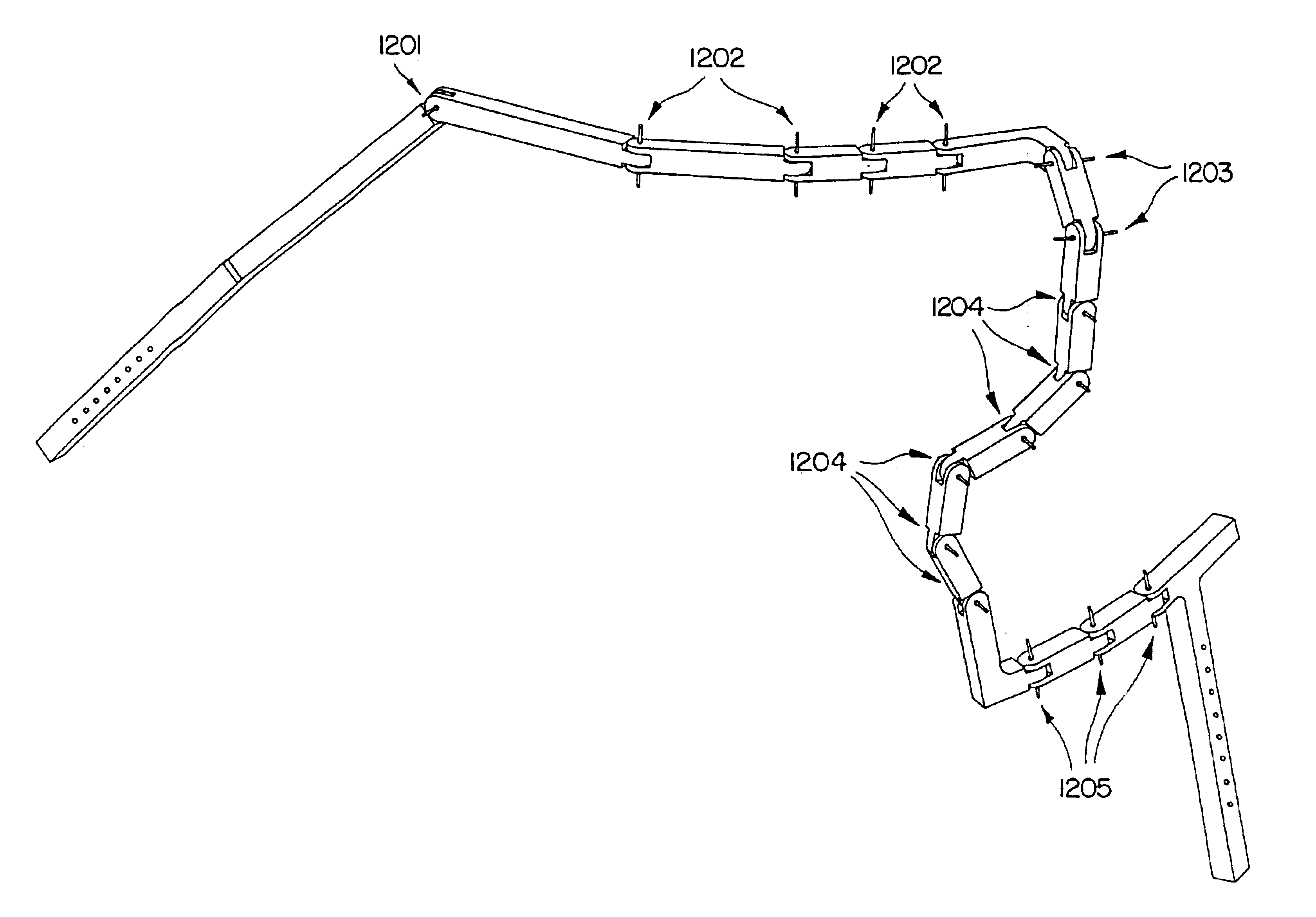
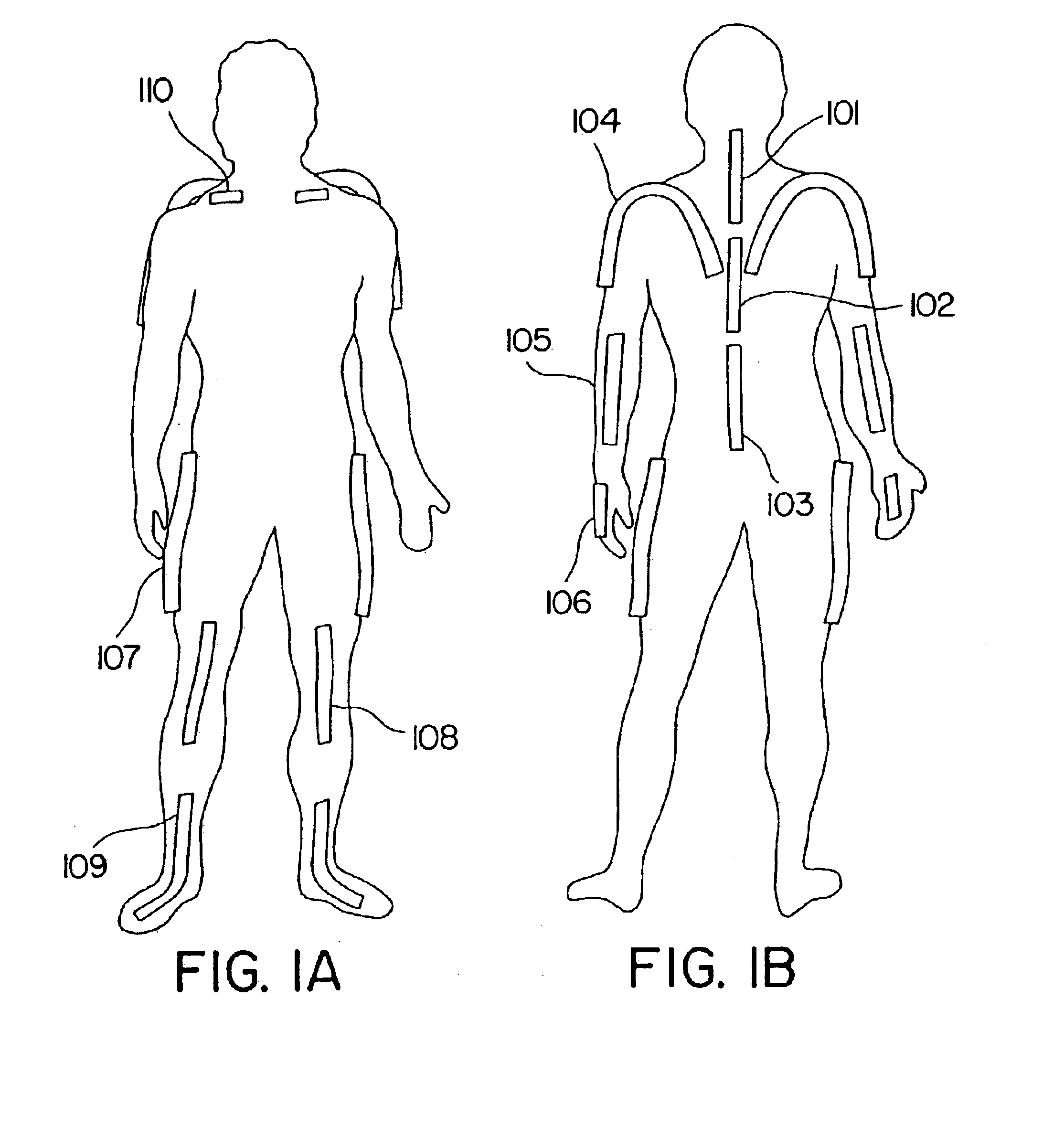
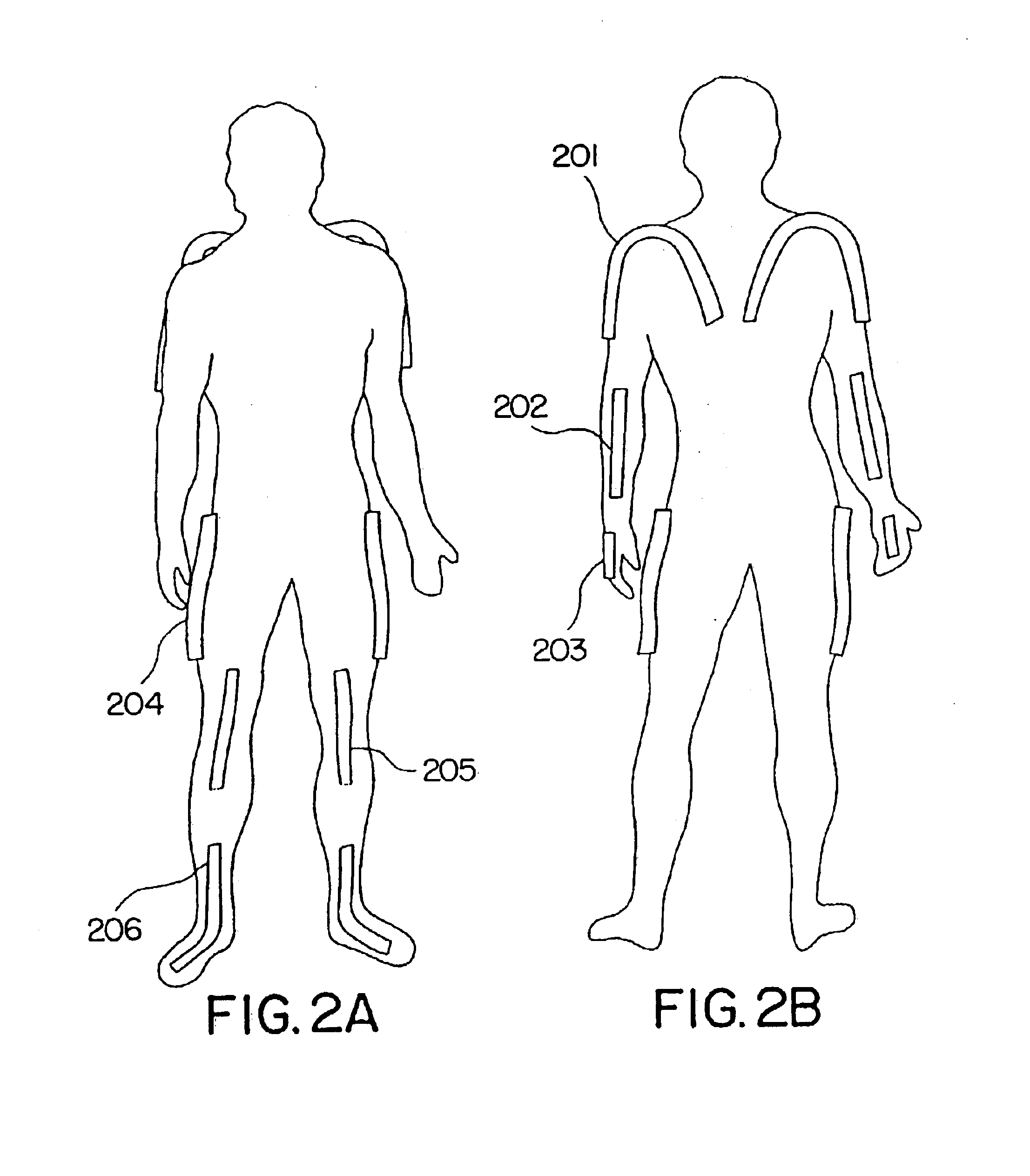
[0082]We now describe an overview of the inventive system and apparatus. In accordance with the subject invention, apparatuses are provided which employ multiple links connected by revolute joints, for measuring body parts, usually human body parts. The link and revolute joint assembly has terminal links for fitting to mounts for the body parts. The mounts secure the terminal links to the body part to minimize movement of the terminal links independent of the movement of the body part. Sensors are provided, where the sensor may extend past a plurality of joints or the sensor ma...


PUM


Abstract

A sensing system is provided for measuring various joints of a human body for applications for performance animation, biomechanical studies and general motion capture. One sensing device of the system is a linkage-based sensing structure comprising rigid links interconnected by revolute joints, where each joint angle is measured by a resistive bend sensor or other convenient goniometer. Such a linkage-based sensing structure is typically used for measuring joints of the body, such as the shoulders, hips, neck, back and forearm, which have more than a single rotary degree of freedom of movement. In one embodiment of the linkage-based sensing structure, a single long resistive bend sensor measures the angle of more than one revolute joint. A second sensing device of the sensing system comprises a flat, flexible resistive bend sensor guided by a channel on an elastic garment.

Description

CROSS-REFERENCE TO RELATED APPLICATIONS[0001]This application is a Continuation of U.S. application Ser. No. 09 / 503,104, filed Feb. 11, 2000, now U.S. Pat. No. 6,428,490, which is a Continuation of U.S. application Ser. No. 09 / 064,637, filed Apr. 21, 1998, now U.S. Pat. No. 6,050,962, which claims the benefit of U.S. Provisional Application Ser. No. 60 / 044,495, filed Apr. 21, 1997 and U.S. Provisional Application Ser. No. 60 / 054,745, filed Aug. 4, 1997.INTRODUCTIONBackground[0002]A growing market has developed for tools and systems that track humans and other bodies at rest and in motion. The applications for such systems vary considerably, and include such areas as the creation of computer-generated and graphical animations, the analysis of human-computer interaction, the assessment of performance athletics and other biomechanics activities, and the evaluation of workplace and other activities for general ergonomical fitness.[0003]The possible sample uses for a body-tracking system...

Claims


Application Information

Patent Timeline
Patent Type & Authority Patents(United States)
IPC IPC(8): A61B5/103A61B5/117G06F3/00G06F3/01
CPCA61B5/1071A61B5/1116A61B5/1122A61B5/1124A61B5/4528A61B5/6831G06F3/011A61B5/6804A61B2562/043A61B5/6806A61B5/6807A61B2562/0261
Inventor KRAMER, JAMES F.ANANNY, JOHN M.BENTLEY, LOREN F.KORFF, PAUL L.BORONKAY, ALLEN R.MCNAMARA, CONOR
Owner IMMERSION CORPORATION
Why Eureka
Try Eureka