Die-expanded molding apparatus and method for synthetic resin, and die-expanded molded foam obtained thereby

a technology of die-expanded molding and die-expanded foam, which is applied in the direction of woodworking apparatus, transportation and packaging, and other domestic objects, which can solve the problems of failure to mold, large difference between the packing density of starting material beads at specific locations in the cavity 104 and the packing density at other locations, and extremely uneven packing. , to achieve the effect of preventing local increases in packing density, and preventing defects in the return flow

Inactive Publication Date: 2006-07-04
DAISEN IND CO LTD +1
View PDF10 Cites 6 Cited by
  • Summary
  • Abstract
  • Description
  • Claims
  • Application Information

AI Technical Summary

Benefits of technology

[0037]In this molding apparatus, while the starting material beads are supplied on a current of air into the cavity by the starting material bead supply means, the air supplied into the cavity is expelled from the cavity by the air expulsion means, allowing the starting material beads to be packed in the cavity, but since the air expulsion means has at least two systems, which are independently controlled, the starting material beads can be packed in areas, for example, where the packing density tends to be lower, allowing the packing density in various parts of the molded product to be regularized, the starting material beads can be packed first in areas where greater strength and rigidity are desired, allowing the packing density to be locally increased in those areas, and the packing density in various parts of the molded product can be adjusted to suitable levels without increasing the number of packers, even in molded products which have parts where the packing density tends to be lower, such as thin-walled parts.
[0071]The density in various parts of the die-expanded molded foam pertaining to the present invention is adjusted to within ±5% of the mean density, preferably within ±4%, more preferably within ±3%. Such a molded product was considered difficult to form in the past, but can be produced according to the aforementioned die-expanded molding methods. The time of the heating and cooling cycles during molding can be shortened, and thin-walled parts and the like with satisfactory strength and rigidity can be ensured, while lighter molded products can be produced.

Problems solved by technology

One problem in particular which needs to be remedied in such a molding method, however, is the considerable difference between the packing density of the starting material beads at specific locations in the cavity 104 and the packing density at other locations.
In these two cases, the current of air acting as the advancing force for packing the starting material beads settles in these portions, which makes it difficult for the starting material beads to be packed all the way into the interior of the recesses 112 or 113 having a pouch-shaped cross section and results in drawbacks such as extremely uneven packing or, in the worst cases, unsuccessful molding due to packing defects.
Efforts have been made to arrange special packers for recesses that are difficult to pack in order to remedy such problems, but they have resulted in the inconvenience of increasing the amount of air that is used, or in the need to reduce the number of molded foam articles which can be formed per mold, with the problem of considerably lowered productivity.
That is because the number of packers that can be attached per molding apparatus is usually limited to a certain extent because of the volume of the starting material tank, the supply capacity of the pressurized air, and the like.
In addition, the increase in the amount of air supplied to the cavity per unit time when the number of packers is increased results in a sudden drop in the air pressure in the cavity immediately after packing and the like, and slows down the expulsion of air from the cavity, and the like, causing all the more variation in packing density.
The number of packers used and the arrangement of the packers are thus a concern for designers of molds, and a great many elements require trial and error, making standardization extremely difficult to achieve in this field.
However, when the hot steam pressure is increased in parts with such low packing density, the parts with a high packing density become overheated, resulting in expansion pressure which is higher than that during normal molding.
Thus, when the molded product is cooled, a longer time is needed to reduce the high expansion pressure to an expansion pressure allowing the molded product to be removed from the mold, and the longer molding cycle leads to a drop in productivity.
Furthermore, the uneven expansion pressure in the various parts of the molded product during heating or cooling results in poor mold releasability and poor packing properties, and thus in the problems of lower productivity and yields.
In cracked packing, on the other hand, the core mold and cavity mold are not completely closed, and are left open to an extent equal to about 10% of the floor thickness of the molded product, for example, so the outer peripheral distal end of the cavity does not form a dead end, but since the core mold and cavity mold are closed after being packed, the density in the floor portion of the molded product is higher than that in other portions to an extent corresponding to the cracked gap, resulting in a separate problem of irregular density.
Additionally, when the two molds are completely closed after being packed with the starting material beads in cracked packing, the outer peripheral distal end of the cavity forms a dead end, resulting in the following problems when the starting material beads are heated by steam and cooled by cooling water to remove the molded product from the mold.
In any type of conventional packing method, however, the parts of the expanded molded foam corresponding to the location of the aforementioned starting material bead supply hole 122 are subject to the phenomenon of over-packing, resulting in the problems of molded products with defective shapes and defective appearance.
Although measures have been attempted to prevent the build up of lumps of excess starting material beads by adjusting the pressure, spraying angle, time, and the like of the packing air sprayed from the spraying hole 126 in order to prevent such over-packing, further problems that have resulted include a longer blow back treatment time, greater consumption of packing air, and the like, yet the effects on over-packing have still been unsatisfactory, and the problem remains to be solved.

Method used


Image

  • Die-expanded molding apparatus and method for synthetic resin, and die-expanded molded foam obtained thereby
  • Die-expanded molding apparatus and method for synthetic resin, and die-expanded molded foam obtained thereby
  • Die-expanded molding apparatus and method for synthetic resin, and die-expanded molded foam obtained thereby

Examples


first embodiment

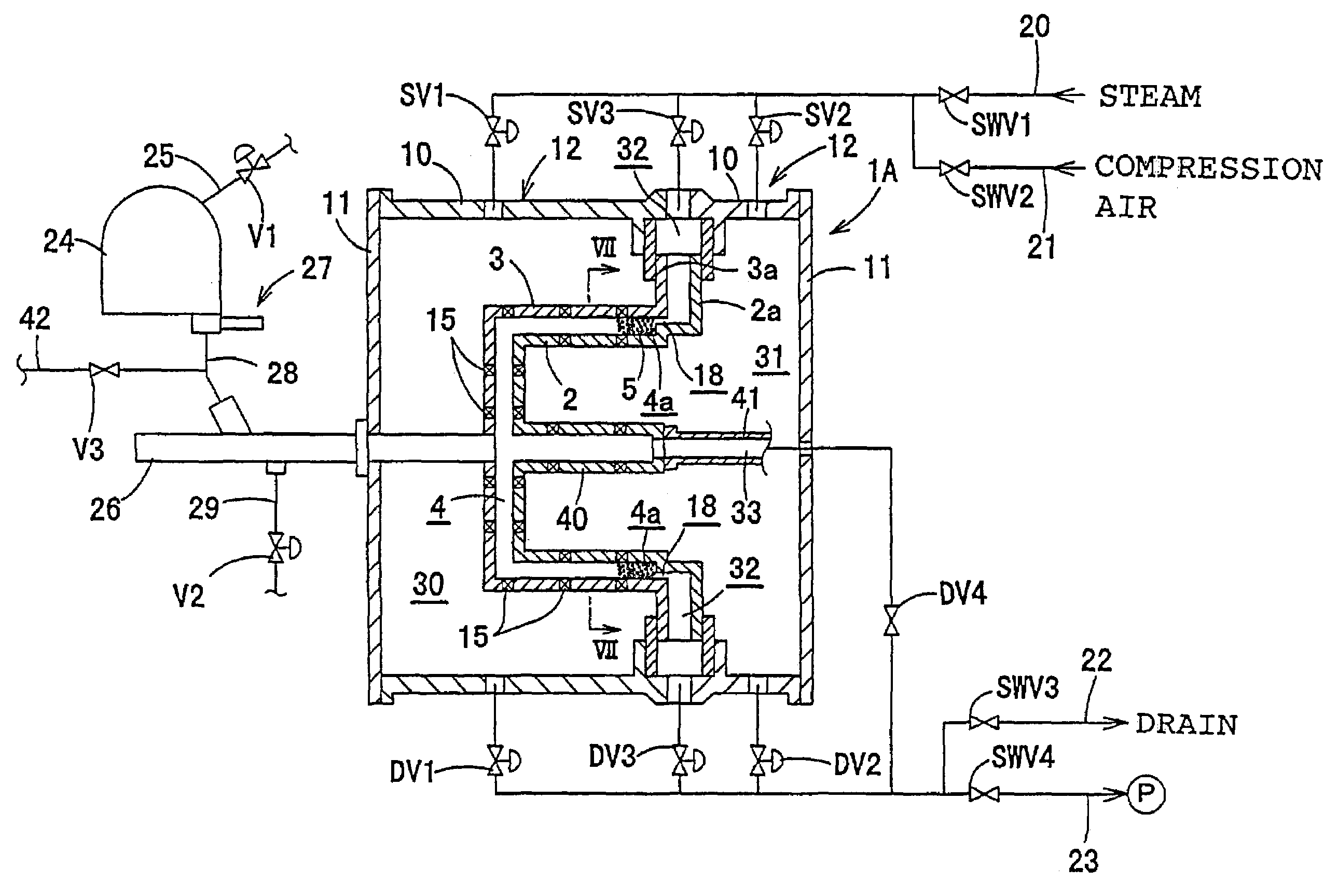
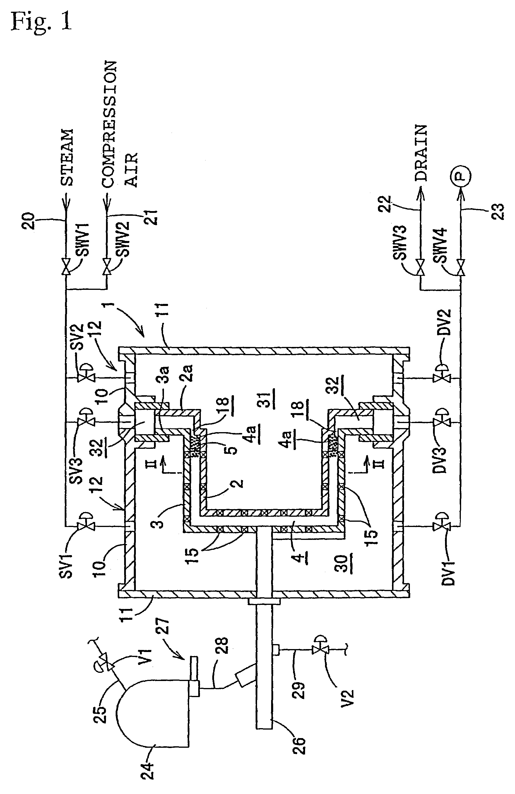
[0164]A feature of the first embodiment is that natural blow back begins when the cavity 4 is filled with the starting material beads 5 thus delivered, such as the state shown in FIG. 12(b), but that blow back is carried out at this time by controlling the pressure in the chamber 30 and 31 to between 0.8 and 1.5 kg / cm2, for example, so that the pressure in the cavity 4 is maintained at a positive pressure as the pressure in the starting material tank 24 is maintained, specifically, is maintained at 1.0 kg / cm2.

second embodiment

[0165]The second embodiment is characterized in that, when natural blow black begins, blow back is carried out by controlling the pressure in the starting material tank 24 to a pressure equivalent to the pressure in the cavity 4, at 0.8 kg / cm2, for example, or to a negative pressure, while maintaining the pressure in the cavity 4, in other words, maintaining the pressure at 0.8 kg / cm2. In this case, the pressure in the starting material tank 24 should be adjusted to between 0.8 and 0.3 kg / cm2.

[0166]The maximum pressure differential of the pressure in the starting material tank 24 relative to the pressure in the cavity 4 must be 0.5 kg / cm2, as indicated in the first and second embodiments.

[0167]In this packing step, natural blow back is carried out under such pressure conditions, the plunger shaft 64 in the plunger 61 is then pushed out in the same manner as in the past, and the starting material bead supply hole 62 of the cavity 4 should be closed off by the plunger tip 65. The expa...


PUM

PropertyMeasurementUnit
diameteraaaaaaaaaa
diameteraaaaaaaaaa
thicknessaaaaaaaaaa

Abstract

A die-expanded molding apparatus comprising starting material bead supply for supplying beads on a current of air from a tank through a packer into a cavity formed by a core and cavity molds; a plurality of air expulsion devices having air pressure-adjusting components communicating with the cavity, a dual-system air expulsion device being such that steam chambers on the back side of the core mold and the cavity mold are used as the air pressure-adjusting components, each communicating with the cavity through through-holes formed in the core and cavity molds, respectively; an air expulsion device having one or more air pressure-adjusting components communicating with a clearance between the core and cavity molds; and a control for controlling the air pressure in each of the air pressure-adjusting components to be pressurized less than the pressure in the tank.

Description

CROSS REFERENCE TO RELATED APPLICATION[0001]This application is a division of Ser. No. 09 / 674,343, filed Oct. 30, 2000, which is a 371 application of PCT Appln. No. PCT / JP99 / 02355, filed Apr. 30, 1999 now abandoned.BACKGROUND OF THE INVENTION[0002]1. Field of the Invention[0003]The present invention relates to a die-expanded molding apparatus and method for synthetic resins, as well as die-expanded molded foam obtained thereby, and more particularly to a technique for improving the packing density of starting material beads in cavities to obtain molded products with more uniform packing density.[0004]2. Description of the Related Art[0005]As shown in FIG. 13, a die-expanded molding apparatus for forming molded products using starting material beads consisting of a thermoplastic synthetic resin comprises a pair of mutually opposed forming molds 100 and 101, and a packer 111 for packing starting material beads in a cavity 104 formed by the two forming molds 100 and 101, where chambers...

Claims


Application Information

Patent Timeline
Patent Type & Authority Patents(United States)
IPC IPC(8): B29C44/02B27N3/08B29C44/44
CPCB29C44/445Y10T428/249953B29C44/3426
Inventor NOHARA, IWAONAKAJIMA, TOMIOIDA, KIYOTAKASAMESHIMA, MASAHIKOKOBAYASHI, YOSHIYUKIYAMAGUCHI, KENJI
Owner DAISEN IND CO LTD
Why Eureka
Try Eureka