
Method and apparatus for processing biomolecule arrays

a biomolecule array and array technology, applied in the field of biomolecule array devices and apparatuses, can solve the problems of poor data quality and reproducibility, low throughput, and difficult reading of arrays in conventional microwells without expensive equipment, and achieve the effect of high data quality

Inactive Publication Date: 2006-07-04
BECKMAN COULTER INC
View PDF18 Cites 91 Cited by
  • Summary
  • Abstract
  • Description
  • Claims
  • Application Information

AI Technical Summary

Benefits of technology

[0007]Given the wide acceptance of “96 head” liquid handling robots and the relative ability to adapt the hybridization process to these robots, there is a need for a high-throughput device that allows microarrays to be processed on robots, and that produces high quality data.
[0014]The microarray plate and the vacuum fixture form a type of titer plate for use with liquid handling robots. The plate and the fixture provide high-throughput array processing, and allow for flat printing surfaces and low well-to-well temperature variations during thermal incubation. The system allows for parallel processing of microarrays in a microtiter plate footprint.

Problems solved by technology

This method, however, suffers from low throughput and poor data quality and reproducibility.
The reading of arrays, however, is difficult in conventional microwells without the use of expensive equipment.
There are also limitations in terms of field of focus and uniform lighting of the bottom of the well using conventional microtiter plates.
In addition, the non-symmetrical design of these plates (solid bottom with open topped wells) results in molded parts that warp due to differential thermal expansion.
As a result, conventional molded titer plates often fail to meet flatness criterion required for array applications.
If the vertical travel is 0.06 inches, then the flatness must be within 0.006 inches, which is often difficult to meet by molded titer plates.
Further, when the plates are heated, warp also creates variable air gaps between the wells and the heating fixture on which the plate is placed.
These air gaps lead to variable thermal resistance from well to well, which leads to difficulties in controlling incubation or hybridization temperature from one array to another.

Method used


Image

  • Method and apparatus for processing biomolecule arrays
  • Method and apparatus for processing biomolecule arrays
  • Method and apparatus for processing biomolecule arrays

Examples


Embodiment Construction

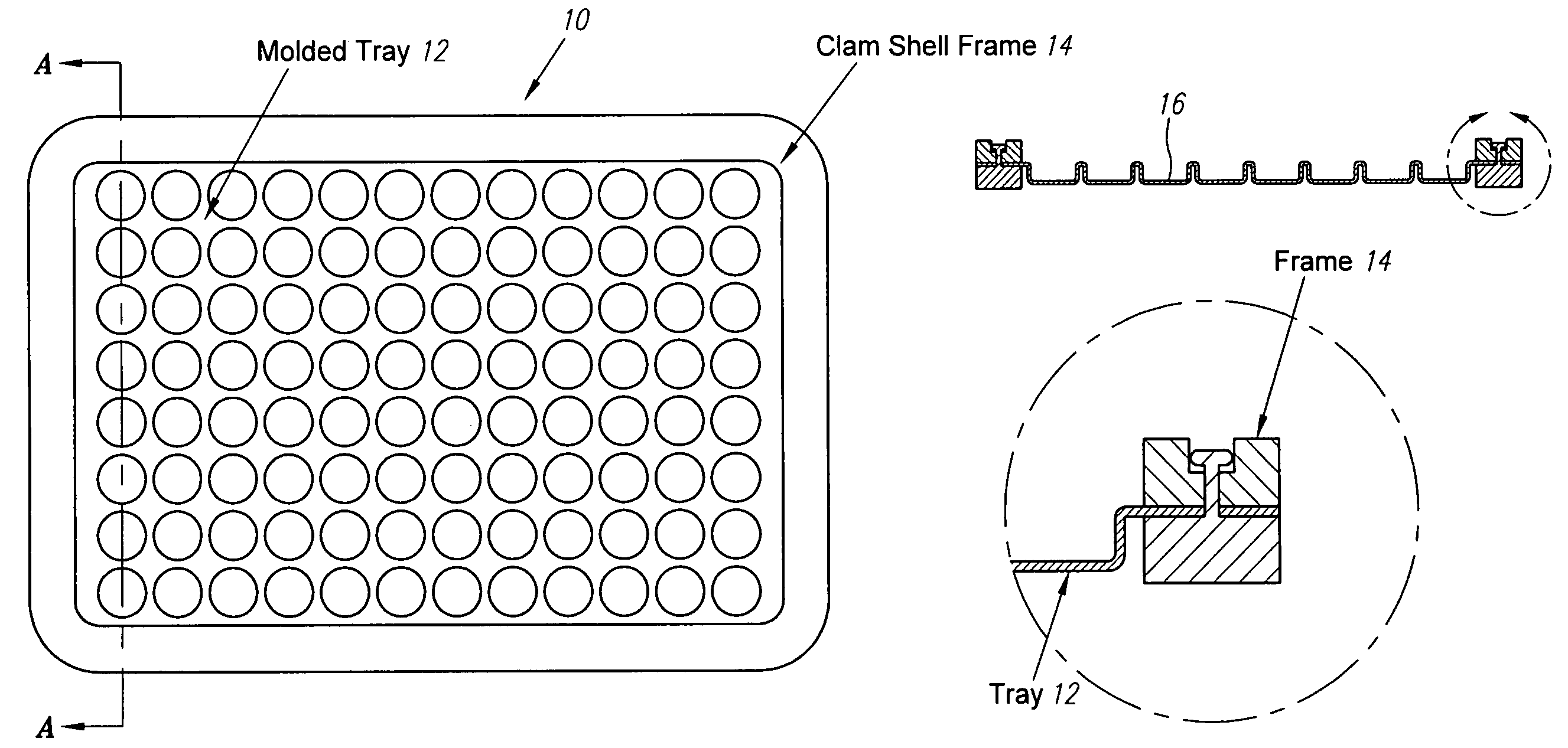
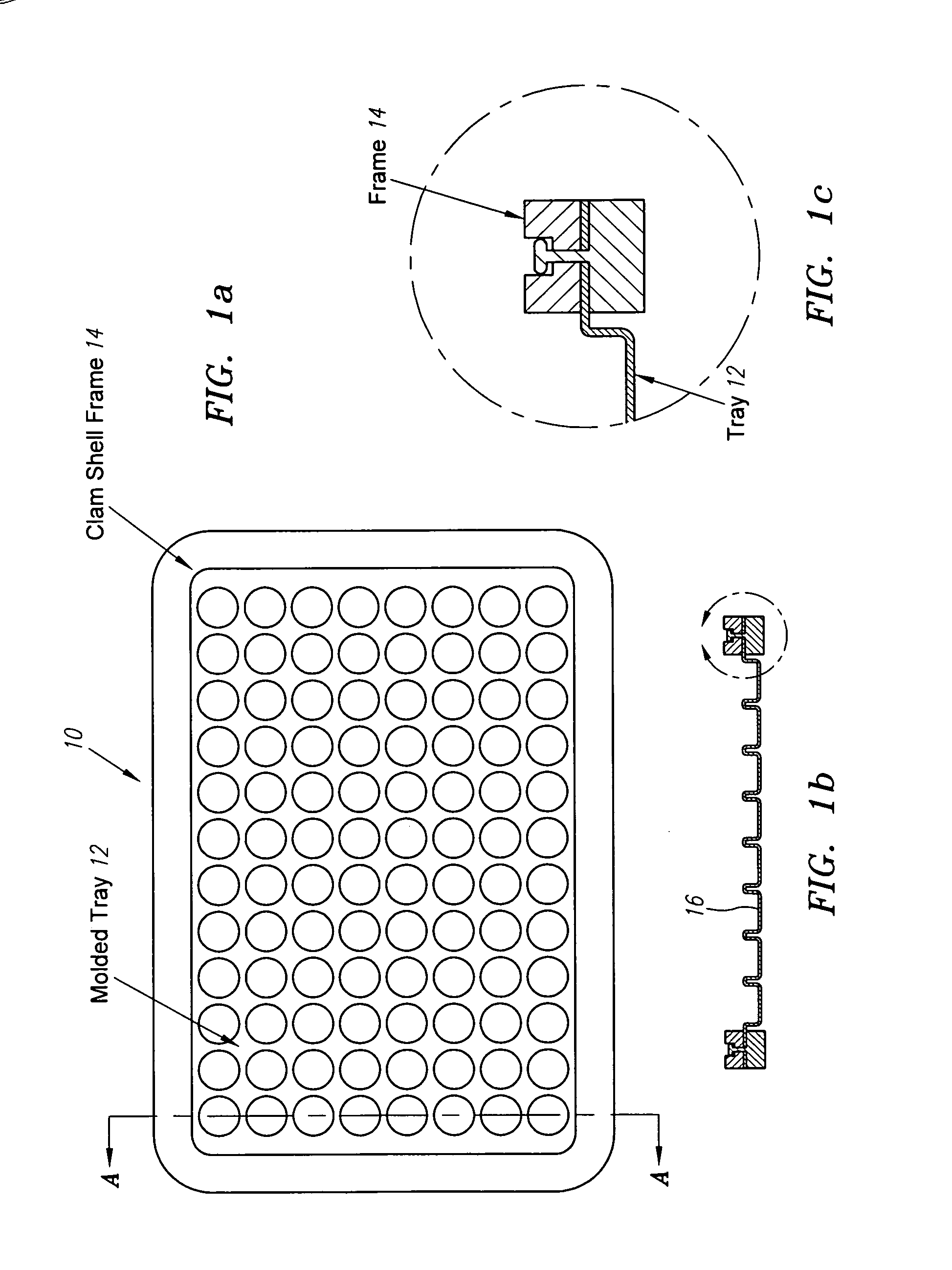
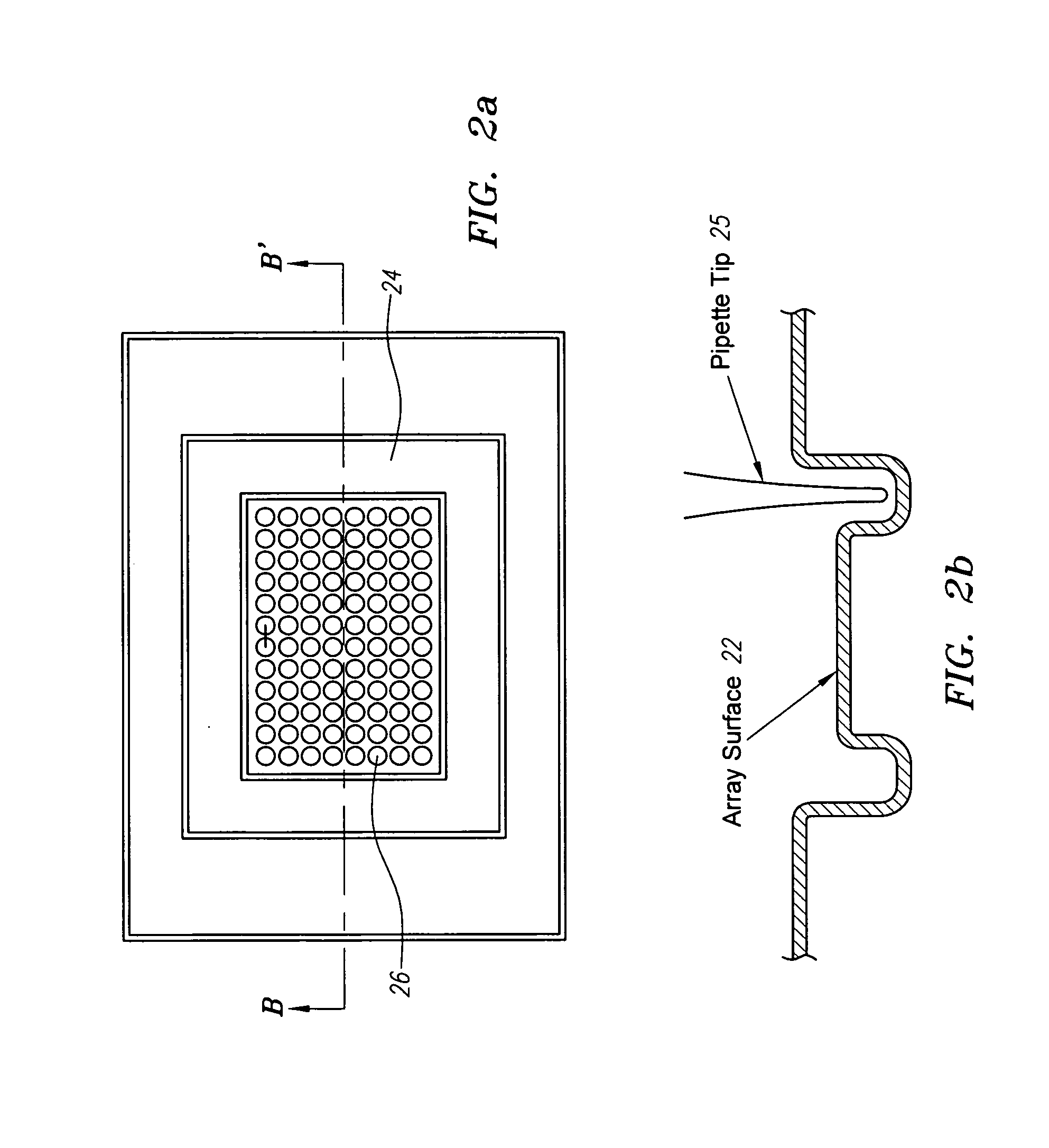
[0029]An array-of-arrays microplate (“A2 plate”) assay system according to the present invention employs an A2 plate in conjunction with devices for microarray printing, liquid handling, hybridization and other processes, and necessary fixture apparatus for adapting the A2 plate to the above devices. The A2 plate is a device comprised of multiple wells, where the wells are discrete areas separated by barriers such as walls, hydrophobic patches, troughs, gaskets or pedestals, etc. that restrict fluid cross-flow between the discrete areas. Within each well may be formed an array of a immobilized elements, where an element is defined as a discrete, physical location of biorecognition materials. The number of elements in an array may be from 1 to 1536 or more, and preferably 16 to 400. The size of the arrays may be the same or different in different wells. The elements in each array may contain the same or different biorecognition materials.

[0030]Biorecognition materials generally refer...


PUM


Abstract

A microarray assay system using an array-of-arrays plate mounted on the top surface of a vacuum fixture, and an automatic handling system that handles the plate and fixture assembly. The A2 plate includes a tray formed of a flexible material and a rigid frame for mounting on the fixture. The fixture has a plurality of orifices opening at the top surface and connected to a vacuum source to create a negative pressure to hold the flexible plate against the top surface of the fixture. The automatic handling systems that can be used with the plate and fixture assembly include a microarray printing machine, liquid handling robot, hybridization and incubation devices, and microarray imaging devices.

Description

BACKGROUND OF THE INVENTION[0001]1. Field of the Invention[0002]This invention relates to device and apparatus for processing biomolecule arrays, and in particular, to an “array of arrays” microplate and an automated processing system. The invention is applicable to DNA diagnostics, mutation screening, gene expression monitoring, protein analysis, cell-based assays and other applications using a robotics workstation.[0003]2. Description of the Related Art[0004]Microarrays such as DNA, oligo, and protein microarrays are becoming a standard tool for monitoring changes in gene expression. This technique has found rapidly growing use in many molecular biology laboratories. A variety of structural and functional genomic characteristics can be studied in addition to expression or transcription. In a Microarrays assay from hundreds to tens of thousands of probes are attached to a substrate in an array form, and sample solutions are incubated on these arrays. By using known sequence of the ...

Claims


Application Information

Patent Timeline
IPC IPC(8): B01L9/00G01N33/53B01J19/00B01L3/00C40B40/06C40B60/14G01N33/543G01N37/00
CPCB01J19/0046B01L3/5085C40B60/14B01J2219/00484B01J2219/00585B01J2219/00596B01J2219/00605B01J2219/0061B01J2219/00621B01J2219/00626B01J2219/00659B01J2219/00662B01J2219/00691B01J2219/0072B01J2219/00722C40B40/06B01J2219/00315
Inventor MATSON, ROBERT S.MORROW, DANIEL G.LOWE, KAREN E.
Owner BECKMAN COULTER INC
Learn More