Electromagnetic circuit and servo mechanism for articulated cameras

a technology of servo mechanism and electromagnetic circuit, which is applied in the direction of magnetic circuit rotating parts, magnetic circuit shape/form/construction, instruments, etc., can solve the problems of minute interruption of video output from the camera, reduce assembly cost, reduce or substantially eliminate interruptions or jumpiness, and increase assembly cost

Inactive Publication Date: 2006-07-04
GE SECURITY INC
View PDF79 Cites 8 Cited by
  • Summary
  • Abstract
  • Description
  • Claims
  • Application Information

AI Technical Summary

Benefits of technology

[0005]In one exemplary embodiment disclosed herein, an electromagnetic circuit and servo mechanism may advantageously employ one or more coil / s to configure a coil assembly that is the only moving component or movable section of the servo mechanism, allowing for both high-speed motion and accurate positioning. In this exemplary embodiment, the magnet assembly is stationary. Because the coil assembly has a lower angular inertial mass than the magnet assembly, it may be used to so configure a movable section of a servo mechanism that is advantageously capable of starting and stopping more quickly than a movable section of a servo mechanism that is configured with a moving magnet assembly. Further advantageously, a coil assembly may be so employed to provide a movable section of a servo mechanism that is much lighter and has much less rotational inertia per given unit height than the moving sections of conventional types of electric motors. As a result of this light inertial mass, the power consumption of the disclosed electromagnetic circuit and servo mechanism may be kept to a minimum. However, it will be understood that any other configuration of coil assembly relative to magnet assembly is possible that is suitable for achieving the features of the electromagnetic circuit and servo mechanism disclosed herein. For example, in an alternate embodiment, the coil assembly may be stationary and the magnet assembly may be the moving component.
[0006]An exemplary four coil assembly configuration is illustrated and described herein. Advantages of such a four coil assembly configuration include reduction or substantial elimination of high torque ripple as the coils switch magnetic phases, a phenomenon that may be experienced with two coil configurations. When a coil assembly is implemented as part of a servo mechanism to drive and articulate the optical block and associated camera assembly of an articulated camera, such magnetic phase switching may cause, for example, a small perturbation to the line of sight (“LOS”) of the articulated camera and hence a minute interruption of video output from the camera due to the non-linear phase transition. The illustrated four coil configuration may thus be employed in one embodiment to achieve cost effectiveness while helping to ensure that torque ripple due to magnetic phase switching is kept to a minimum. However, although illustrated and described herein with reference to an exemplary coil assembly configuration that includes a set of four coils, other coil assembly configurations may be suitably employed in the practice of the disclosed systems and methods, e.g., more than four coils, less than four coils, six or more coils, etc. It will also be understood that any multiple coil arrangement (other than four coil arrangements) helps reduce torque ripple due to magnetic phase switching, e.g., two or more coils. However, a greater number of coils tend to provide greater benefit.
[0008]As disclosed herein, a continuous magnet configuration may be advantageously employed to reduce or substantially eliminate interruptions or jumpiness (e.g., torque ripple) during motor rotation that may occur, for example, when coils rotate across the boundaries of individual separate magnets of a multiple-piece non-continuous magnet configuration. Furthermore, use of a one-piece magnet advantageously reduces assembly cost by eliminating the difficulties associated with aligning discrete separate magnets and the polarity and orientation issues of same that may result in higher assembly cost. In this regard, two or more discrete magnets are typically difficult to assemble because each polarity has to be faced in predefined orientations since the magnets are typically magnetized prior to assembly. In one embodiment, a magnet configured in a continuous shape may be further characterized as a continuous magnet having multiple north-south poles (i.e., a continuous magnet having more than one north pole and having more than one south pole). For example, a continuous magnet may have multiple sets of poles (e.g., more than one set of poles, more than two sets of poles, etc.), with each set of poles including one north and one south pole.
[0009]Thus, in one embodiment of the disclosed systems and methods, an electromagnetic circuit and servo mechanism may be implemented in a manner where there is little or no drive torque fluctuation. In such an embodiment, the coil may be configured to operate inside a uniform magnetic field enabling sub-micron positioning while eliminating noise and cogging. These characteristics are ideal for high-speed, high-precision positioning actuators.

Problems solved by technology

When a coil assembly is implemented as part of a servo mechanism to drive and articulate the optical block and associated camera assembly of an articulated camera, such magnetic phase switching may cause, for example, a small perturbation to the line of sight (“LOS”) of the articulated camera and hence a minute interruption of video output from the camera due to the non-linear phase transition.

Method used


Image

  • Electromagnetic circuit and servo mechanism for articulated cameras
  • Electromagnetic circuit and servo mechanism for articulated cameras
  • Electromagnetic circuit and servo mechanism for articulated cameras

Examples


Embodiment Construction

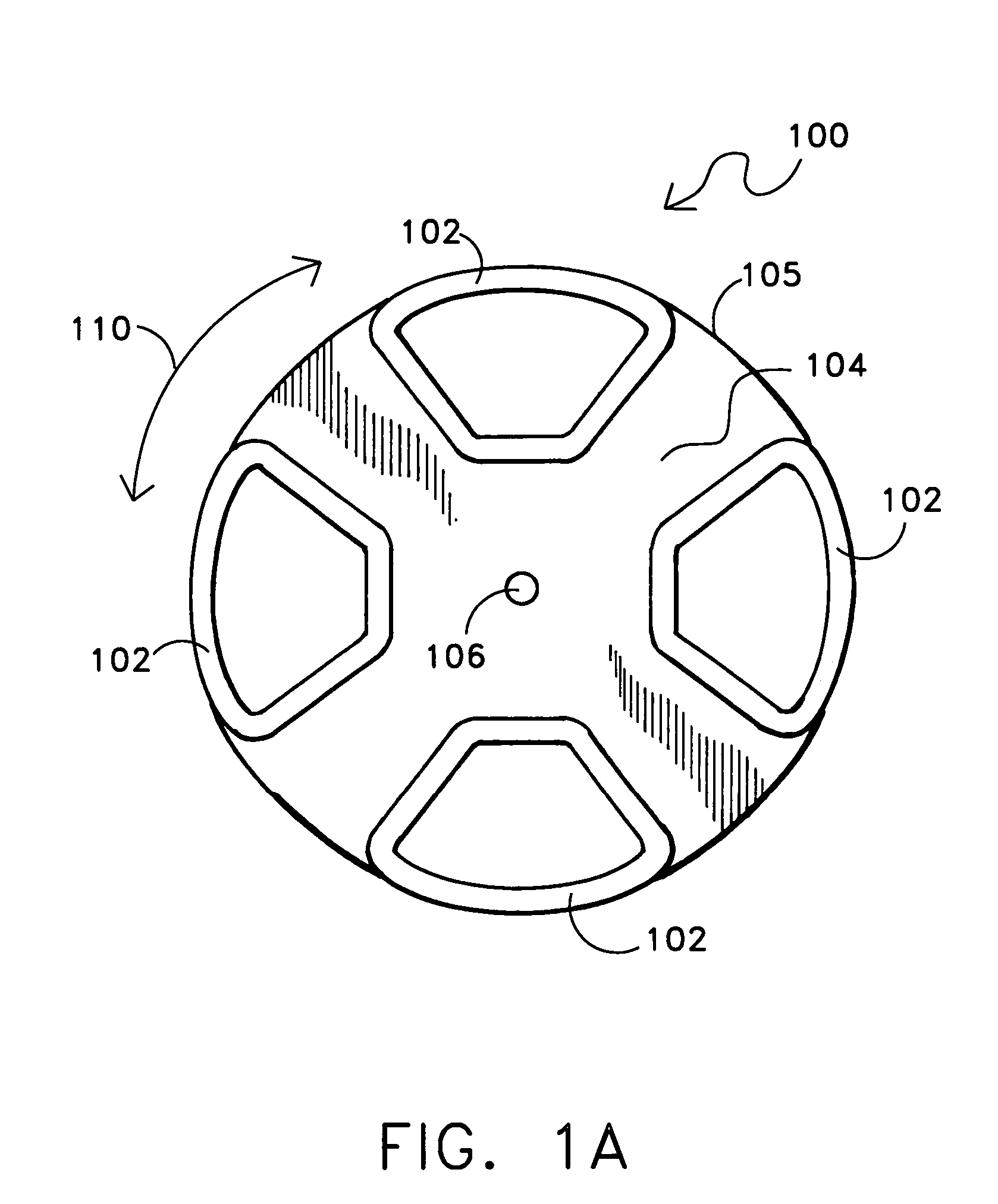
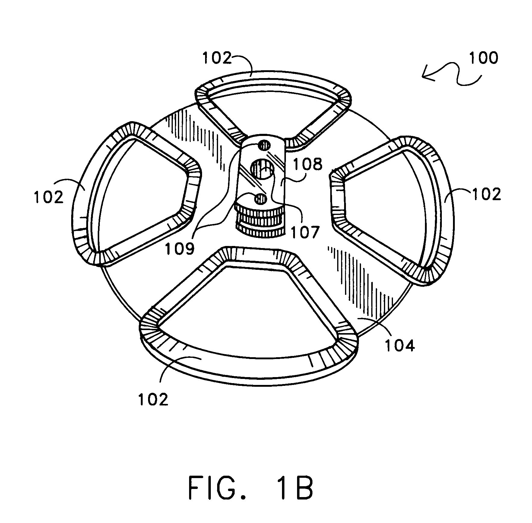
[0031]FIG. 1A illustrates one exemplary embodiment of a multiple coil assembly 100 having four motor coils 102 that are integrated within or otherwise fixedly coupled to a coil support assembly in the form of a circular coil support platter 104. As shown in FIG. 1A, coil support platter 104 may include a rotation point in the form of a central opening 106 for receiving a spindle mechanism in the form of a shaft with or on which coil support platter 104 may rotate in a manner such that rotational motion may be imparted to a drive member (e.g., drive bracket, etc.) by the coil assembly 100. Although an opening 106 is illustrated in FIG. 1A, it will be understood that any other suitable rotation point configuration (e.g., solid platter with more than one attachment point / s for a spindle assembly, etc) may be employed for rotatably coupling a coil support platter to a spindle mechanism that is suitable for allowing a coil assembly to rotate and to transfer rotational motion to a drive m...


PUM


Abstract

An electromagnetic circuit that may be advantageously employed in an articulated camera, such as a CCTV camera, as a part of a servo mechanism to directly drive the camera and optical lens assembly, for example, in the pan and / or tilt axes. In one embodiment, the coil assembly of the servo mechanism may comprise four separate coils that rotate about the center of the ring shape of a single one-piece ring-shaped permanent magnet that has been pre-magnetized in two pair of opposing polarities. The magnet assembly that includes the magnet ring, may be bonded to a circular plate made of ferrous metal.

Description

[0001]This patent application claims priority to copending U.S. Provisional Patent Application Ser. No. 60 / 437,711, filed Jan. 2, 2003, and entitled “ELECTROMAGNETIC CIRCUIT AND SERVO MECHANISM FOR ARTICULATED CAMERAS” by Hovanky, the entire disclosure of which is incorporated herein by reference.BACKGROUND OF THE INVENTION[0002]The present invention relates generally to cameras, and more particularly to articulated cameras such as may be employed in closed circuit television (“CCTV”) applications.[0003]Current articulated camera technology typically relies on conventional stepper or DC motors to drive and articulate the optical block and camera assembly in the pan and tilt axes. Such conventional camera articulation technology typically requires gear or belt drive assemblies to achieve the angular resolution required to articulate the camera and position the lens. Due to the number of gear or belt drive components typically required for such articulated camera applications, the cam...

Claims


Application Information

Patent Timeline
Patent Type & Authority Patents(United States)
IPC IPC(8): H02K21/26H02K23/54H02K25/00
CPCG08B13/1963H02K25/00H02K23/54G08B13/19634
Inventor HOVANKY, THAO D.WASHINGTON, RICHARD G.
Owner GE SECURITY INC
Why Eureka
Try Eureka