Method and apparatus for rendering a cell-based switch useful for frame based protocols

a cell-based switch and frame-based protocol technology, applied in data switching networks, frequency-division multiplexes, instruments, etc., can solve problems such as inacceptable frame transmission time latency

Inactive Publication Date: 2006-07-04
MCDATA SERVICES CORP +1
View PDF19 Cites 37 Cited by
  • Summary
  • Abstract
  • Description
  • Claims
  • Application Information

AI Technical Summary

Benefits of technology

[0015]Data for subsequent cells is accumulated similarly, but it is not necessary to fill the enter data payload of these subsequent cells. Rather, when a cell is to be submitted to the cell-based switch fabric, a partially filled cell is provided. This partially filled cell contains a valid byte count indicating the number of valid data bytes in the data payload. This valid byte count is located in the length of packet cell header field. When these subsequent cells are received at the destination port, only the valid data bytes in the data payload are used to reconstruct the Fibre Channel frame, with the fill bytes being discarded. By allowing partially filled data payloads in the cells, the present invention is able to seamlessly convert between the transmission rate of the data received over the incoming Fibre Channel port and the data rate of the cell-based switch.

Problems solved by technology

The Ethernet switch in the '549 patent did not describe the use of a true cell-based switch, since the shared bus configuration meant it was not possible to simultaneously route a plurality of cells between different pairs of source and destination ports.
However, waiting for the entire frame to be buffered before sending the beginning of the frame over the cell-based switch fabric introduces unacceptable latency into the transmission time of the frame (about 20 microseconds at 1 Gbps data rate versus a preferred maximum latency of two microseconds).

Method used


Image

  • Method and apparatus for rendering a cell-based switch useful for frame based protocols
  • Method and apparatus for rendering a cell-based switch useful for frame based protocols
  • Method and apparatus for rendering a cell-based switch useful for frame based protocols

Examples


Embodiment Construction

Switch Overview

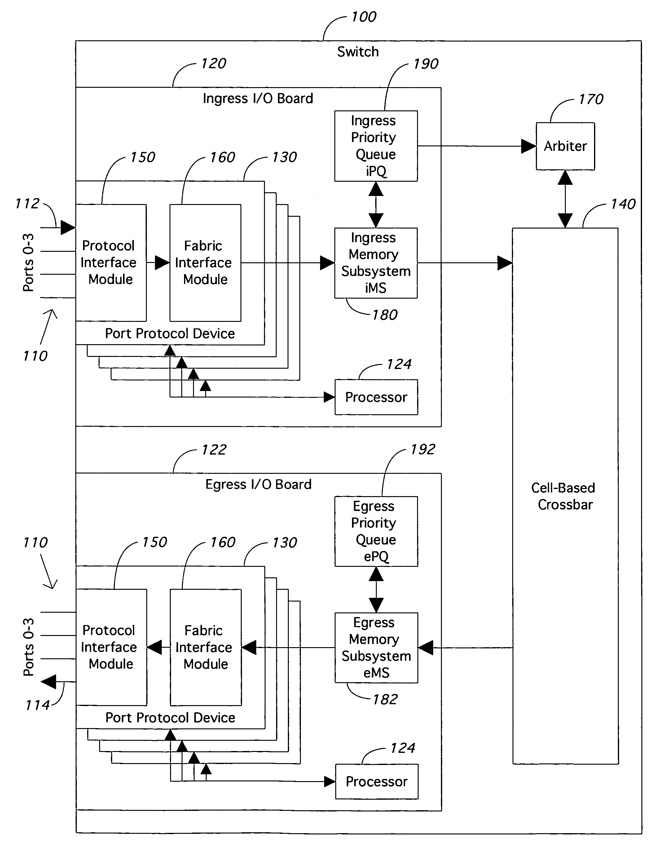
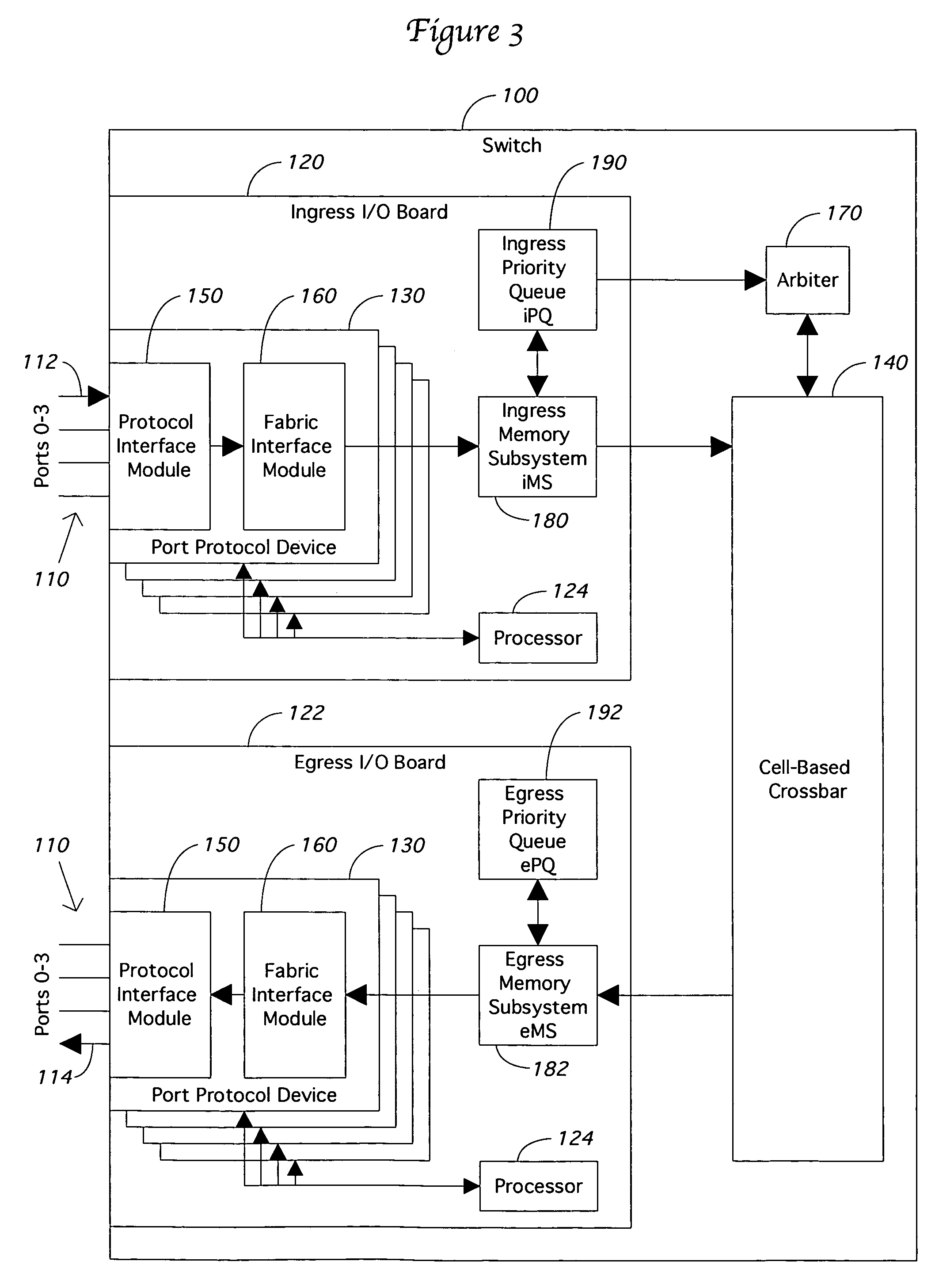
[0027]The present invention is best understood after examining the major components of a Fibre Channel switch, such as switch 100 shown in FIG. 3. The components shown in FIG. 1 are helpful in understanding the applicant's preferred embodiment, but persons of ordinary skill will understand that the present invention can be incorporated in switches of different construction, configuration, or port counts.

[0028]Switch 100 is a director class Fibre Channel switch having a plurality of Fibre Channel ports 110. The ports 110 are physically located on one or more I / O boards inside of switch 100. Although FIG. 3 shows only two I / O boards, namely ingress board 120 and egress board 122, a director class switch 100 would contain eight or more such boards. The preferred embodiment described in the application can contain thirty-two such I / O boards 120, 122. Each board 120, 122 contains a microprocessor 124 that, along with its RAM and flash memory (not shown), is responsible for...


PUM


Abstract

A switch segments variable length frames into cells for transmission over a cell-based switch fabric and handles rate differences between the input data rate and the switch fabric data rate. The fabric handles multiple cell packets by maintaining a switch path until a certain number of cells are transmitted as indicated in a length field in the first data cell. The first cell contains a full data payload, and a length field value sufficient to handle a maximum length frame. Subsequent cells can contain less than a full data payload, with the number of valid bytes in the cell being indicated in the length field. The last cell used to segment the frame contains an end of frame indicator. The indicator signals the destination port side of the switch to terminate the packet path in the switch fabric prematurely—before the number of cells indicated in the first data cell.

Description

RELATED APPLICATIONS[0001]This application is a continuation-in-part application based on U.S. patent application Ser. No. 09 / 995,605, entitled “Method and Apparatus for Rendering a Cell-Based Switch Useful for Frame Based Application Protocols,” filed Nov. 29, 2001, which is hereby incorporated by reference and which claims the benefit of U.S. provisional application No. 60 / 297,454, filed Jun. 13, 2001.[0002]This application is related to U.S. patent application entitled “Fibre Channel Switch,” Ser. No. 10 / 873,532, filed on Jun. 21, 2004. This related application is hereby incorporated by reference.FIELD OF THE INVENTION[0003]The present invention relates generally to products and methods that are capable of reducing latency in switches. More particularly, it relates to a method and system for reducing latency and handling data rate differences in cell-based switch fabrics adapted for use with Fibre Channel or other frame-based protocols.BACKGROUND OF THE INVENTION[0004]Fibre Chann...

Claims


Application Information

Patent Timeline
Patent Type & Authority Patents(United States)
IPC IPC(8): G06F11/00H04J3/16H04L12/56H04Q11/04
CPCH04Q11/0478H04L12/5601H04L49/1576H04L49/3081H04L49/608H04L2012/5665H04L2012/5651H04Q2213/1302H04Q2213/1304H04Q2213/13103H04Q2213/13216H04Q2213/13296H04Q2213/1332H04L2012/5605H04L2012/5627H04L2012/5681H04L49/357H04L47/6275H04L49/25
Inventor PAUL, HARRY V.GONZALEZ, HENRY O.CANTWELL, LARRY
Owner MCDATA SERVICES CORP
Why Eureka
Try Eureka