Line-narrowed gas laser system

a laser system and gas laser technology, applied in laser details, microlithography exposure apparatus, active medium materials, etc., can solve the problems of not having an option, not being so often used by catadioptric systems as conventional dioptric systems, and chromatic aberration correction, etc., to achieve the effect of improving the capability of line narrowing

Active Publication Date: 2006-07-04
GIGAPHOTON +1
View PDF12 Cites 20 Cited by
  • Summary
  • Abstract
  • Description
  • Claims
  • Application Information

AI Technical Summary

Benefits of technology

[0042]In view of such problems with the prior art as described above, it is a general object of the present invention to provide a gas laser system using an F2-containing laser gas, for instance, a KrF laser system, an ArF laser system, and an F2 laser system, which has improved line-narrowing capability. A particular object of the present invention is to provide a line-narrowed F2 laser system wherein the ASE is cut off to achieve a spectral linewidth of 0.2 pm or lower and a spectral purity of 0.5 pm or lower.
[0066]said controller stores ahead data on progression over time of a spectral linewidth and / or a spectral purity of light making round trips in the laser resonator and a time Tbw obtained from the data, at which values of a given spectral linewidth and / or a given spectral purity are obtained with an origin defined by a starting point of the discharge emission waveform, and receives data from the discharge emission detector to determine therefrom a time TSL1 of generation of a first peak of the discharge emission waveform with an origin defined by the starting point of the discharge emission waveform, so that at least one of the voltage applied to the electrodes, the concentration of F2 in the laser and the laser gas pressure in the laser chamber is controlled to foreclose a possibility of TSL1<Tbw, thereby allowing a laser beam to have the given spectral linewidth (FWHM) and / or the given spectral purity at a point of time of generation of a laser beam to emerge from the laser resonator.
[0071]said controller stores ahead data on progression over time of a spectral linewidth and / or a spectral purity of light making round trips in the laser resonator and a time Tbw obtained from the data, at which values of a given spectral linewidth and / or a given spectral purity are obtained with an origin defined by a starting point of the discharge emission waveform, and receives data from the laser pulse detector to determine therefrom a time TLPS of generation of a laser pulse waveform with an origin defined by the starting point of the discharge emission waveform, so that at least one of the voltage applied to the electrodes, the concentration of F2 in the laser and the laser gas pressure in the laser chamber is controlled to foreclose a possibility of TLPS<Tbw, thereby allowing a laser beam to have the given spectral linewidth (FWHM) and / or the given spectral purity at a point of time of generation of a laser beam to emerge from the laser resonator.
[0081]According to the present invention, the rise of the sidelight is made so gentle that the starting point of a laser pulse can exist after the point of time of the first peak of the sidelight, thereby cutting off the ASE. It is thus possible to achieve a line-narrowed F2 gas laser system having a spectral linewidth of 0.2 pm or lower and a spectral purity of 0.5 pm or lower. It is also possible to achieve a KrF laser system and an ArF laser system having improved line-narrowing capability.
[0082]To provide a high output, line-narrowed molecular fluorine laser system, it is possible to make use of an injection lock type arrangement or an MOPA arrangement, wherein the rise of the sidelight is made so gentle in an oscillation-stage laser including a line-narrowing means that the starting point of a laser pulse can exist after the point of time of the first peak of the sidelight, thereby obtaining a spectral linewidth of 0.2 pm or lower and a pulse energy of 5 mJ or higher.
[0083]To provide a high output, line-narrowed KrF or ArF laser system, it is possible to make use of an injection lock type arrangement or an MOPA arrangement, wherein the rise of the sidelight is made so gentle in an oscillation-stage laser including a line-narrowing means that the starting point of a laser pulse can exist after the point of time of the first peak of the sidelight, thereby obtaining a spectral linewidth that is narrower than the linewidth needed for an aligner and a pulse energy of 5 mJ or higher.

Problems solved by technology

One grave problem with photolithography is how to correct chromatic aberrations in an optical system.
By virtue of some limitations on the types of available optical materials transparent to a wavelength range in the neighborhood of 157 nm, however, there is now no option but to use CaF2 (fluorite).
However, the catadioptric systems are not so often used as conventional dioptric systems by virtue of difficulties with the optical axis alignment of aligners.
Even when such an optical line-narrowing module having a spectral function in the laser resonator is used as the line-narrowing means for a line-narrowed F2 laser system, it is still difficult to narrow its spectral linewidth (FWHM) to 0.2 pm or less demanded for the dioptric system of an aligner.
When it comes to an aligner light source, however, there are some limitations on system size at a worksite and, hence, some limitations on the size of a line-narrowing module used thereat.
Thus, there are limits to increasing the number of expanding prisms and the width of the diffraction grating.
There are also limits ascribable to optical part fabrication techniques.
For instance, the blaze angle cannot possibly be larger than a predetermined value because of limits to diffraction grating fabrication.
Even with pulse stretching, however, it is still difficult to narrow the spectral linewidth (FWHM) to 0.2 pm or less.
With the laser pulse waveform containing the ASE, on the other hand, it is difficult to satisfy the specifications of an aligner light source in terms of spectral purity.
It is thus impossible to satisfy the specifications regarding the spectral purity although depending on what is demanded for an aligner.
While the values of the spectral linewidth and spectral purity demanded vary with wavelenth, it is understood that such problems as mentioned above arise with KrF and ArF laser systems.

Method used


Image

  • Line-narrowed gas laser system
  • Line-narrowed gas laser system
  • Line-narrowed gas laser system

Examples


Embodiment Construction

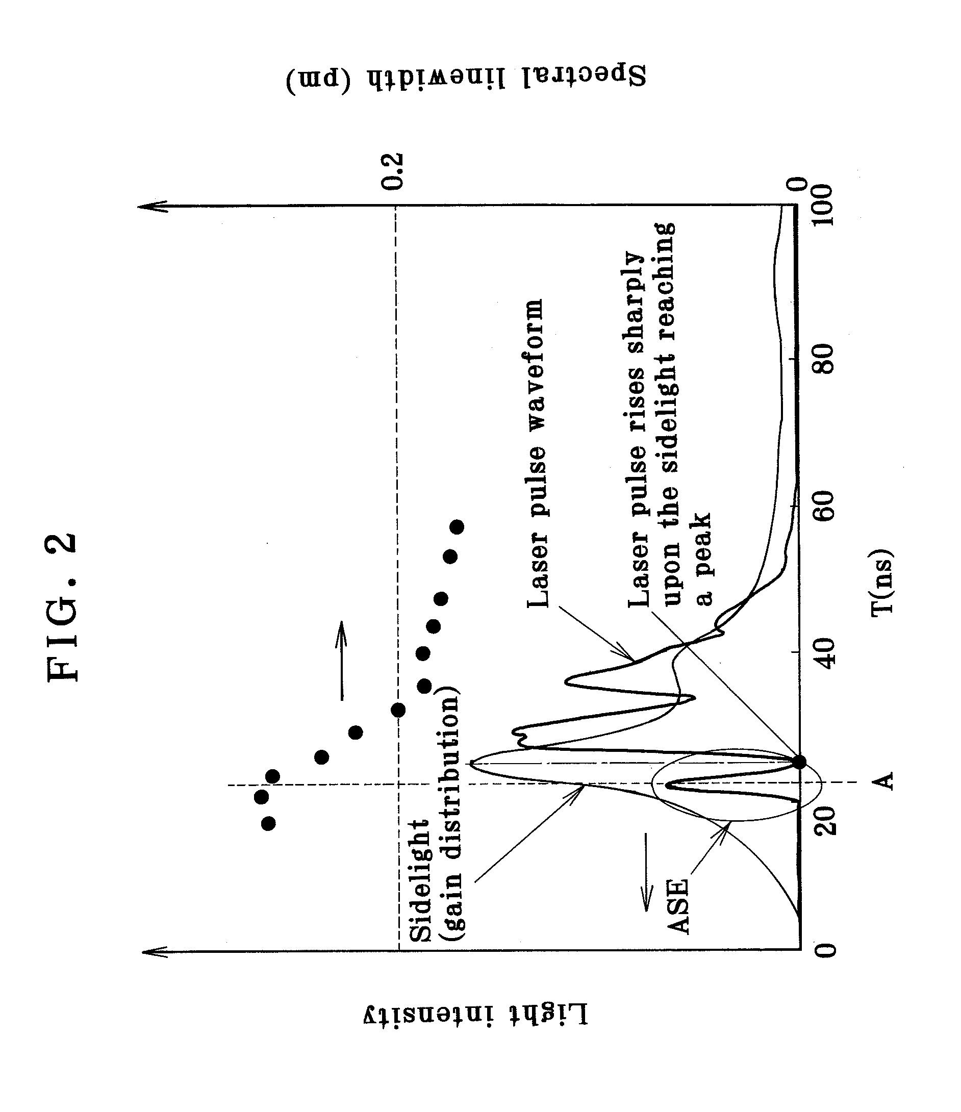
[0113]From the summary of the invention, it is understood that to achieve a spectral linewidth of 0.2 pm or less and a spectral purity of 0.5 pm or less, it is required to cut off or remove the ASE component from light emitted out of the line-narrowed F2 laser system. It is also understood that to improve line-narrowing capability, it is necessary to cut off or remove the ASE component light emitted out of the line-narrowed KrF or ArF laser system.

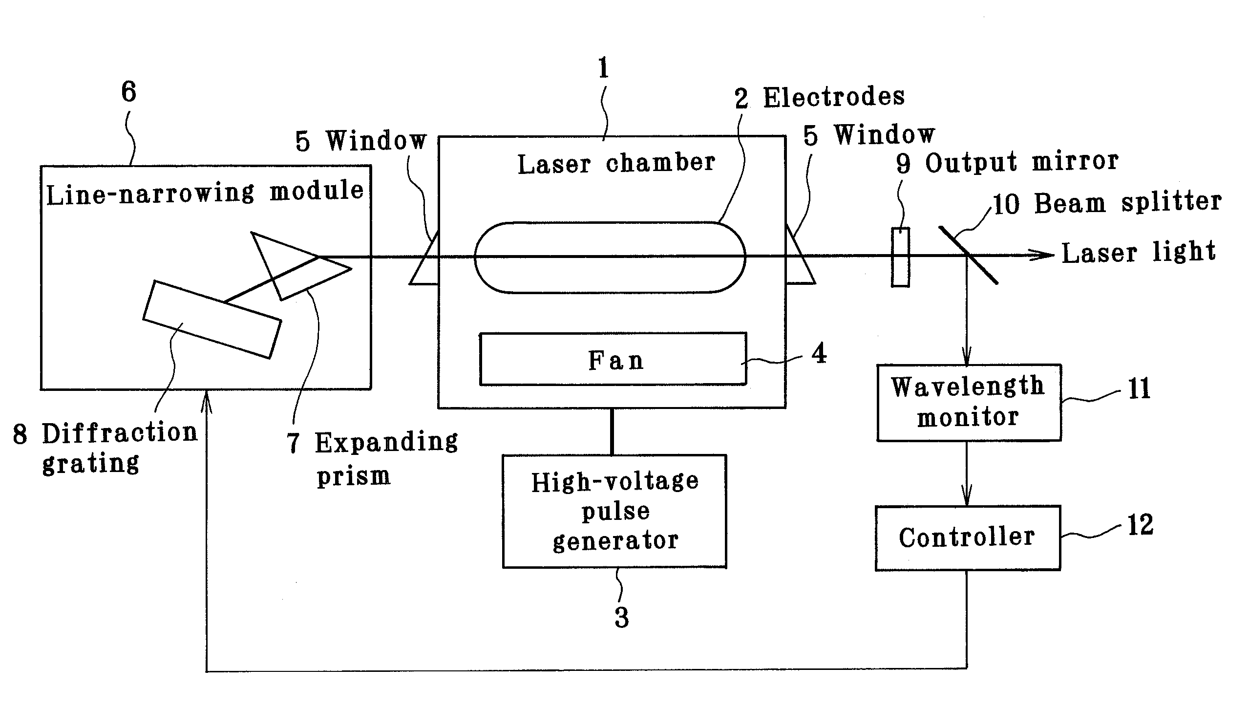
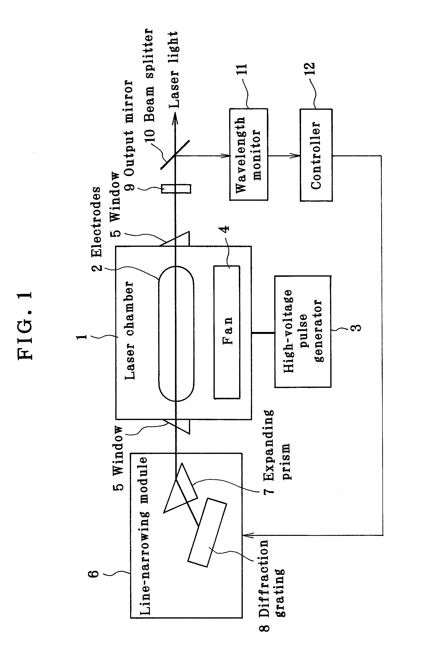
[0114]As a consequence of intensive and extensive studies made by the inventors, it has now been found out that to cut off or remove the ASE component from light emitted out of a line-narrowed F2 laser system such as one shown in FIG. 1, it is effective to make the rise of laser gain gentle and delay the rise starting point of time of a laser pulse. This is also found to hold true for line-narrowed KrF, and ArF laser systems. The present invention is now explained specifically with reference to the line-narrowed F2 laser system.

[0115]FIG. ...


PUM

PropertyMeasurementUnit
wavelengthsaaaaaaaaaa

Abstract

In a line-narrowed gas laser system such as a line-narrowed molecular fluorine laser system, ASE is cut off to obtain a spectral linewidth of 0.2 pm or lower and a spectral purity of 0.5 pm or lower. The laser system comprises a laser chamber filled with an F2-containing laser gas, discharge electrodes located in the laser chamber, a laser resonator and a line-narrowing module located in the laser resonator with a wavelength selection element, so that a line-narrowed laser beam emerges from the laser resonator. To cut off ASE from the laser beam emerging from the laser resonator, the duration from laser emission by discharge to generation of a laser beam is preset. Rise of the sidelight is made so gentle that the starting point of a laser pulse can exist after the time of the first sidelight peak.

Description

BACKGROUND OF THE INVENTION[0001]The present invention relates generally to a line-narrowed gas laser system, and more particularly to a gas laser system such as an F2 laser system in which laser beams are narrowed to a spectral linewidth of 0.2 pm or lower and a spectral purity of 0.5 pm or lower while ASE (amplified spontaneous emission) is substantially cut off from the laser beams.[0002]The present invention is also concerned with a gas laser system using laser gases inclusive of F2, for instance, a KrF or ArF laser system, in which the ASE is cut off from laser beams, thereby making spectral linewidths and spectral purities by far narrower.[0003]As semiconductor integrated circuits become increasingly fine with increasing packing densities, aligners used for their fabrication are now required to have stronger resolving power than ever before. It is in turn required to make shorter the wavelengths of exposure light emitted from exposure light sources. To this end, semiconductor ...

Claims


Application Information

Patent Timeline
Patent Type & Authority Patents(United States)
IPC IPC(8): H01S3/22G03F7/20H01L21/027H01S3/134H01S3/139H01S3/225
CPCH01S3/134H01S3/225H01S3/139
Inventor ARIGA, TATSUYASEKI, KYOHEIWAKABAYASHI, OSAMU
Owner GIGAPHOTON
Why Eureka
Try Eureka