Intelligent load distribution system

a load distribution system and intelligent technology, applied in the field of intelligent load distribution system, can solve the problems of increasing the risk of an accident, reducing vehicle performance, and significantly altering the handling, performance and fuel efficiency of load over a trailer

Inactive Publication Date: 2006-07-04
ARVINMERITOR TECH
View PDF29 Cites 50 Cited by
  • Summary
  • Abstract
  • Description
  • Claims
  • Application Information

AI Technical Summary

Benefits of technology

[0017]In this way, the inventive information system provides a vehicle driver with the opportunity not only to determine his current load distribution but to adjust components of the vehicle as well as load within the vehicle to optimize the vehicle for performance as well as to comply with state and federal load limit requirements.

Problems solved by technology

The distribution of load over a trailer significantly alters its handling, performance, and fuel efficiency.
Improper loading of a trailer not only reduces vehicle performance but also increases the risk of an accident.
Additionally, state and federal laws impose load limits on tractor / trailer combinations.
Failure to comply with such limits can lead to the imposition of fines or other penalties.
They do not provide information on how load should be distributed.
While these foregoing methods provide basic information about the distribution of weight over a tractor / trailer, they do not provide information on how to optimize the distribution of weight to comply with load limits or to enhance vehicle performance.
Moreover, the measurements offered by these foregoing methods of determining load distribution are not integrated or analyzed with other vehicle characteristics that affect vehicle maneuverability and handling, such as tire pressure, axle position, or trailer height.
Load distribution is accordingly not optimized for performance.
However, the repositioning of the slider in these instances may result in a less than optimal slider position for other operational situations.

Method used


Image

  • Intelligent load distribution system
  • Intelligent load distribution system
  • Intelligent load distribution system

Examples


Embodiment Construction

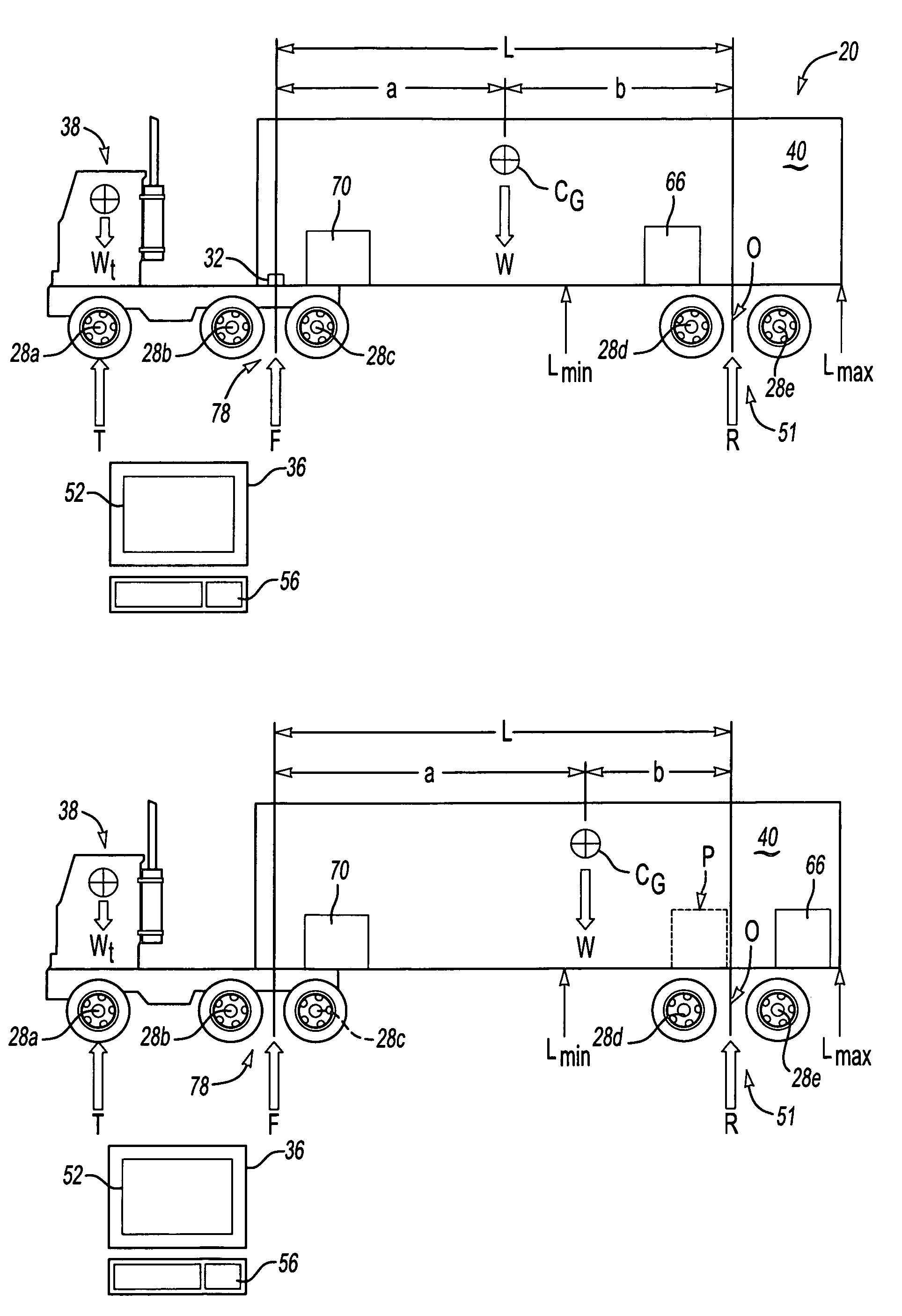
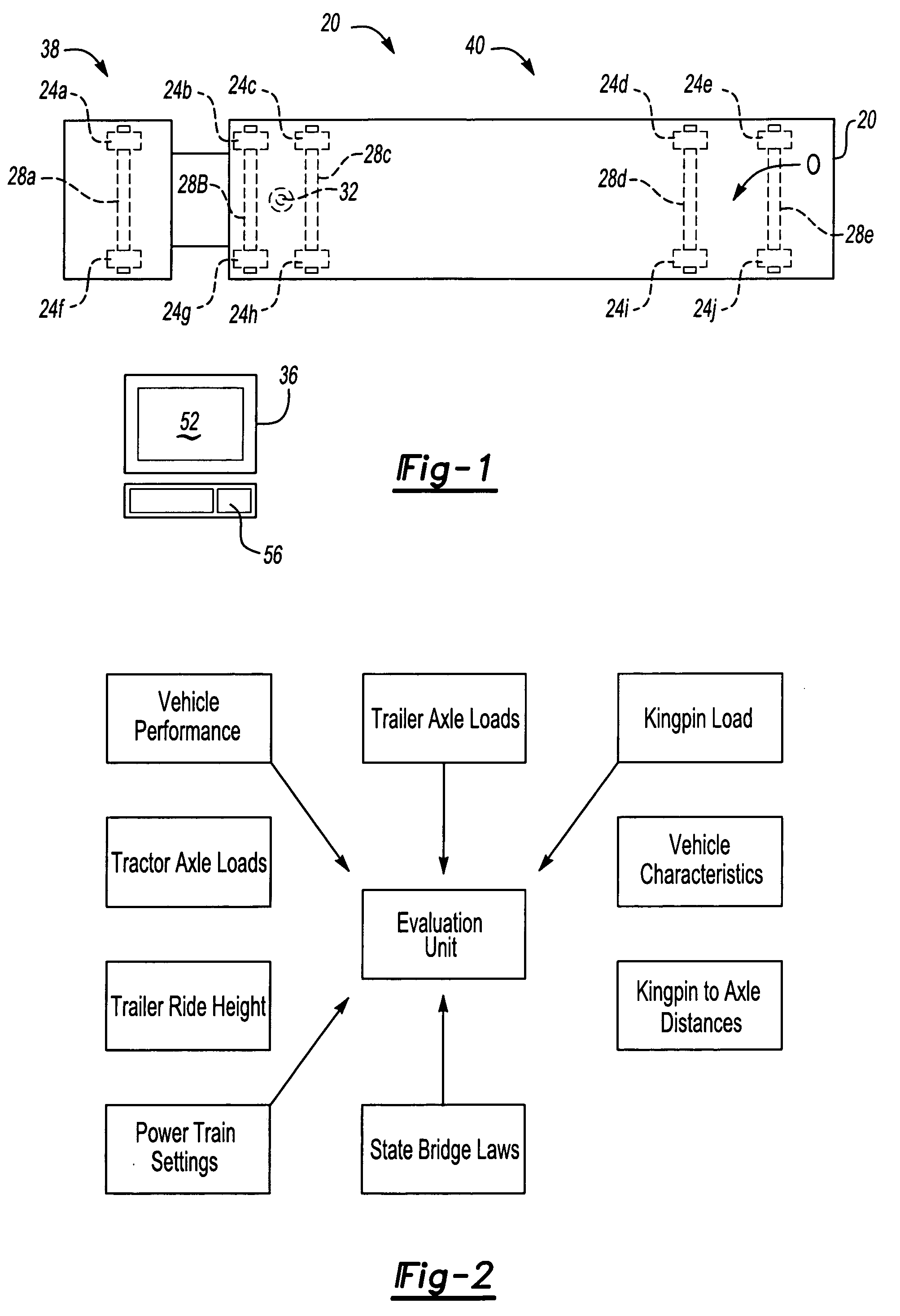
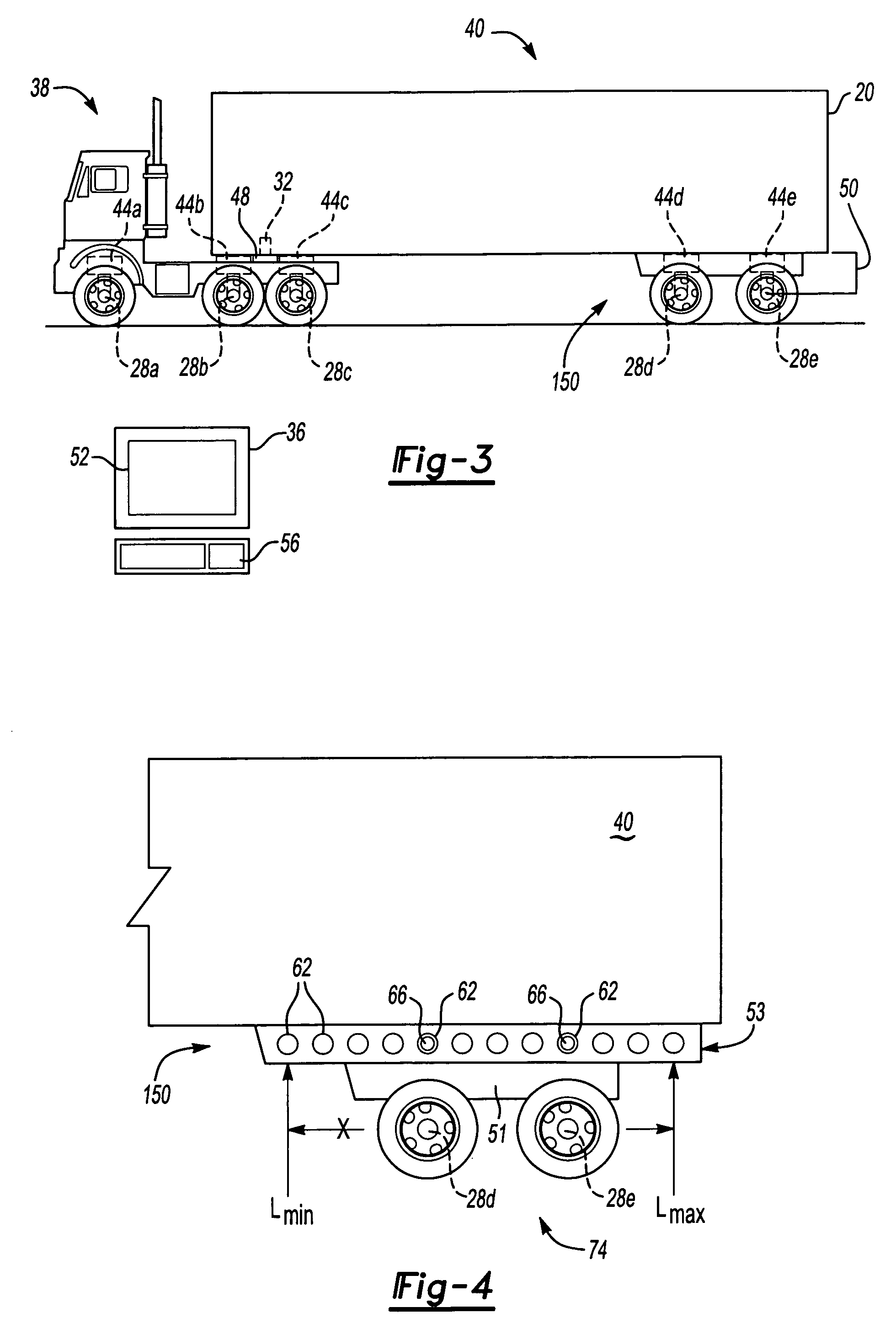
[0027]FIG. 1 presents an embodiment of the invention. As known in the prior art, systems exist that measure the distribution of load across a vehicle such as tractor / trailer 20, as seen in FIG. 1. These systems employ at least one or a plurality of load sensors 24A–J to determine the load over axles 28A–E as well as kingpin 32, the mechanical pivoting pin link between the tractor and trailer. Such sensors may include load cells, piezo electric film sensors, or strain gauges. Pressure sensors measuring load on a vehicle's air suspension can also function as load sensors. Readings from load sensors 24A–b J are then used to determine load distribution across tractor 38 and trailer 40.

[0028]While readings from load sensors 24A–J provide basic information concerning load distribution, such as weight over axles 28A–E or even total weight of tractor / trailer 20, a tractor / trailer driver must determine for himself whether his load is in compliance with state and federal law load limits or wh...


PUM


Abstract

A vehicle information system has a first load sensor for generating a first load signal based on a first vehicle load. A first position sensor generates a first position signal based on a position of a vehicle axle. A second position sensor generates a second position signal based on a position of a vehicle kingpin. A memory unit stores vehicle optimization data. An evaluation unit is in communication with the first load sensor, the first position sensor, the second position sensor and the memory unit. A general user interface for receiving input is also in communication with the evaluation unit. The evaluation unit makes an evaluation of the first load signal, the first position sensor, the second position signal, and any input and generates a vehicle optimization instruction relating to a distance between the axle and the kingpin.

Description

[0001]This patent application is a continuation-in-part and claims priority to U.S. Nonprovisional Patent Application No. 09 / 724,373 filed on Nov. 28, 2000, now abandoned.BACKGROUND OF THE INVENTION[0002]This invention relates to a system for determining and optimizing load distribution on a vehicle.[0003]The distribution of load over a trailer significantly alters its handling, performance, and fuel efficiency. Braking, acceleration, turning, as well as operational safety of the vehicle are all affected by load distribution. Improper loading of a trailer not only reduces vehicle performance but also increases the risk of an accident.[0004]Additionally, state and federal laws impose load limits on tractor / trailer combinations. Limits exist on maximum weight, weight over an axle, and weight over a tandem axle. These limits vary from state to state, requiring a driver to know whether he is in compliance with these limits as he crosses each state line. In the event a load exceeds these...

Claims


Application Information

Patent Timeline
Patent Type & Authority Patents(United States)
IPC IPC(8): G01G19/08G01G15/00
CPCG01G19/086
Inventor SAXON, NANCY L.ECKELBERRY, JAMESMA, JOHN K.MALY, JR., FRANK A.MELEKIAN, JOSEPHMILLER, STEVEN R.SOMNAY, RAJESH J.
Owner ARVINMERITOR TECH
Why Eureka
Try Eureka