Apparatus, methods, and liners for repairing conduits

a conduit and lining technology, applied in the field of apparatus, methods, liners for repairing conduits, can solve the problems of insufficient flexibility of needle-punched felt material to conform well to the surrounding pipe wall, affecting the confluence between the main line and the intersecting side line, and affecting the quality of linings

Inactive Publication Date: 2006-07-11
VERLINE INSTALLATION INC +1
View PDF36 Cites 36 Cited by
  • Summary
  • Abstract
  • Description
  • Claims
  • Application Information

AI Technical Summary

Benefits of technology

[0019]In one embodiment the present invention is directed to an apparatus for repairing an intersection between a first conduit and a second conduit. The apparatus comprises a body or support structure for transporting repair material containing a heat curable resin to the intersection of the first conduit and the second conduit. The repair material is structured to conform to the shape of the intersection. The body includes an inflation device that is connected to and carried by the body. The inflation device is capable of compressing the repair material to at least a portion of the intersection. For example, the inflation device may be a tubular inflatable bladder that compresses a portion of the repair material against the interior of the second conduit adjacent the intersection. The inflation device includes conductive fibers capable of electrically resistively heating the inflation device to effect curing of the resin in the repair material. These fibers could be metallic or may be of a non-ferrous material.

Problems solved by technology

The cause of leakage can vary from improper installation to environmental conditions to normal aging or the detrimental effects of the substances transported on the pipe materials.
Regardless of the cause, leakage is undesirable.
In conditions where the intersecting angles of the main pipe and the lateral pipe constitute an obtuse angle, as typically encountered in a convention sewer “wye”, a needle-punched felt material does not possess the necessary flexibility to conform well to the surrounding pipe walls.
Even after much effort and expense has been expended on the remediation of these systems, the areas of confluence between the main lines and intersecting side lines (hereinafter called laterals) has only minimally been addressed.
This has resulted in many failures due to premature curing of the resin, inadequate resin cross-linking and shrinkage.
In addition, because the resin is applied to the repair material at the installation site, inconsistencies in both resin content and mixing procedures can be expected.
The shortcomings of these types of systems lay in the difficulty of the prescribed radiant light source to penetrate through the thickness of the repair material and the overall fragility of such devices.
Another problem is encountered with repairing pipes having large diameters.
If the ambient temperature is too low, which is common with underground conduits, the resin will not completely cure and the liner can collapse.
In contrast, if the ambient temperature is too high, the resin can cure prematurely, that is before the liner is properly located in the damaged portion of the conduit.
There are a number of disadvantages to curing a liner with hot water or steam.
First, the equipment required to heat the water or to create steam is extremely expensive and inefficient.
Second, curing with either fluid requires a temperature ramp-up, which consumes long periods of time.
Curing a liner with hot water, steam, or ambient is also negatively affected by heat sink in the conduit.
In addition, heat sink can prevent the complete curing of all resin in the liner, thereby reducing the strength and durability of the liner.
These factors reduce both the cost efficiency and process efficiency of hot water, steam, and ambient cure.
The conventional liners used to repair large diameter conduits are very thick and generally require a large amount of resin.
The large amount of resin exacerbates the need for ramped temperatures and as a result, further increases curing times while reducing the efficiency of the repair.
Due to their large size and weight, liners for large diameter conduits are difficult to handle and maneuver within the damaged conduit.
Also, liners for large diameter conduits are more susceptible to the negative effects of heat sink.

Method used


Image

  • Apparatus, methods, and liners for repairing conduits
  • Apparatus, methods, and liners for repairing conduits
  • Apparatus, methods, and liners for repairing conduits

Examples


Embodiment Construction

[0054]While this invention is susceptible of embodiments in many different forms, there is shown in the drawings and will herein be described in detail preferred embodiments of the invention with the understanding that the present disclosure is to be considered as an exemplification of the principles of the invention and is not intended to limit the broad aspect of the invention to the embodiments illustrated.

Conduit Intersection Repair:

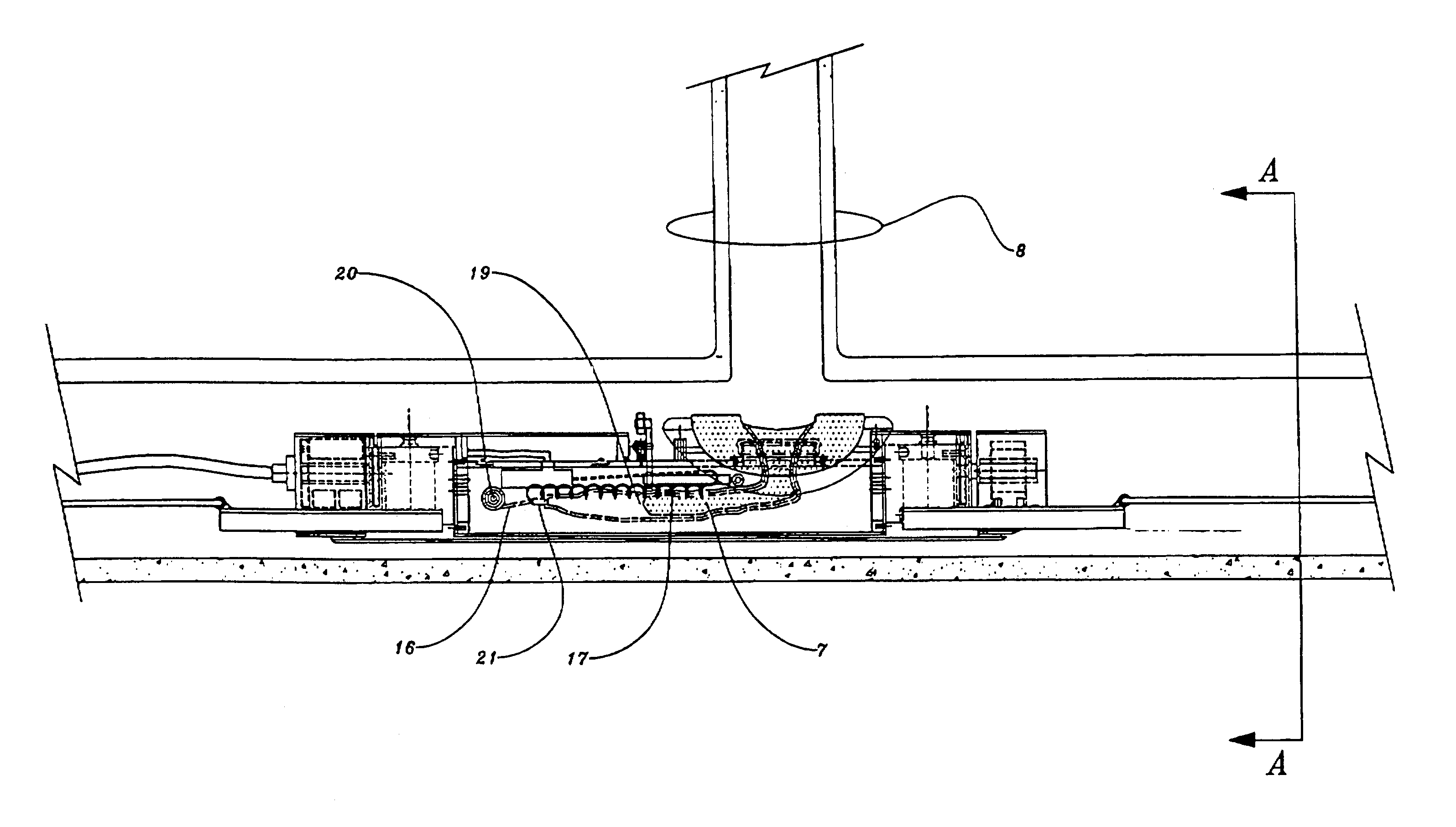
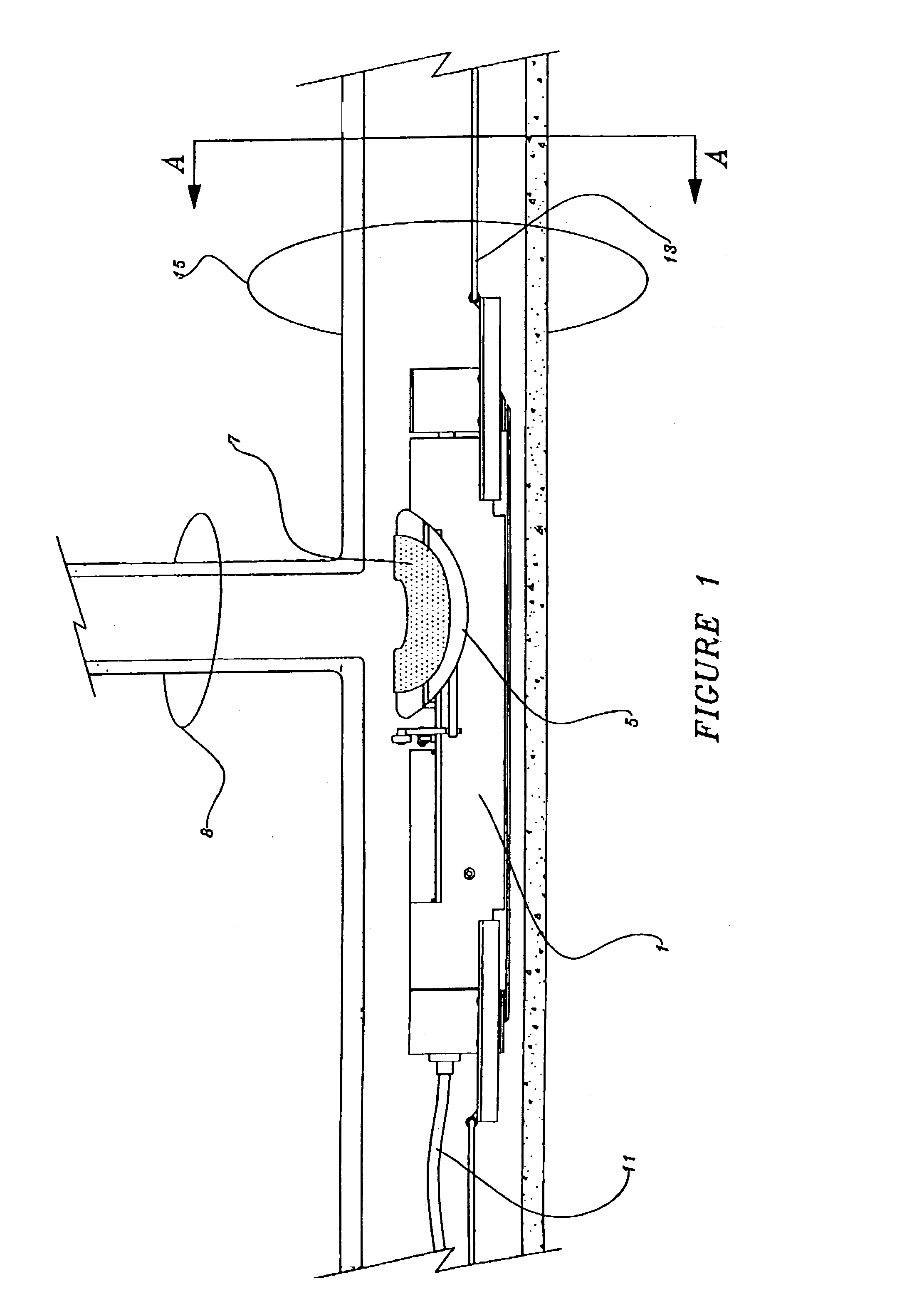
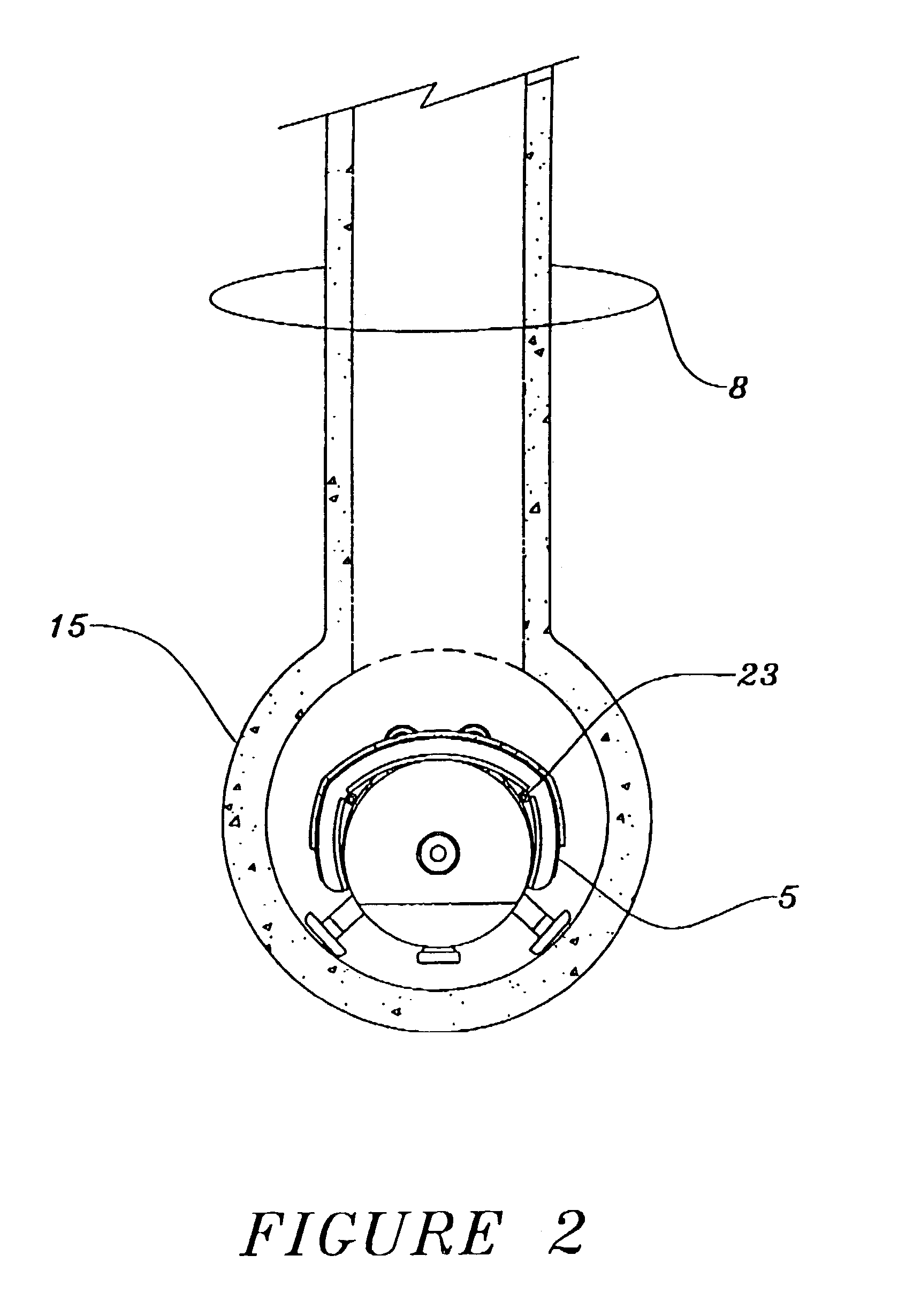
[0055]A preferred embodiment of the apparatus of the present invention is depicted in FIG. 1. In accordance with the invention, the apparatus includes a main body 1 that is positioned in a first conduit 15. The first conduit 15 may be pipe forming a main line of a sewer system. The main line 15 intersects a second conduit or lateral line 8. Lateral line 8 is shown here in a perpendicular position essentially at a 90° angle to the main line pipe and intersects the main line pipe at the top portion. This condition is typical but may also be arranged in...


PUM

PropertyMeasurementUnit
diametersaaaaaaaaaa
water temperatureaaaaaaaaaa
angleaaaaaaaaaa

Abstract

An apparatus and method for repairing the juncture or intersection of a first conduit and a second conduit is disclosed. The apparatus includes a main body for transporting and positioning a repair material impregnated with at heat curable resin system or matrix. An inflation device carried within the main body positions and compresses the repair material against the intersection. This includes a portion of the interior of the second conduit and flange portion in the first conduit. The inflation device includes conductive fibers that are electrically conductively heated to effect curing of the resin in the repair material.

Description

RELATED CASES[0001]“This Application is a U.S. National filing under §371 of International Application No. PCT / US01 / 03498, filed 2 Feb. 2001, claiming priority from U.S. Ser. Nos. 60 / 179,806 (filed Feb. 2, 2000), 60 / 179,687 (filed Feb. 2, 2000) and 60 / 179,686 (filed Feb. 2, 2000), (which are hereby incorporated by reference).”TECHNICAL FIELD[0002]The present invention generally relates to an apparatus and method for the installation of a repair material within a conduit or pipe such as a sanitary sewer line. More specifically, the invention pertains to an apparatus and method for the installation of a repair material at the intersecting junction between two transversely opposed pipes or conduits.[0003]The present invention also relates to a method and apparatus for repair of large diameter sanitary sewer pipe or conduit. Specifically, the invention pertains to an advanced method and liner apparatus for the in-situ repair of conduits having large diameters.[0004]Additionally, the pre...

Claims


Application Information

Patent Timeline
Patent Type & Authority Patents(United States)
IPC IPC(8): F16L55/16B29C53/58B29C63/00B29C63/34E03F3/06F16L55/165F16L55/168F16L55/179
CPCB29C63/0069B29C63/34E03F3/06F16L55/265F16L55/1654F16L55/1656F16L55/168F16L55/179B29C53/58B29L2023/006E03F2003/065
Inventor BLACKMORE, RICHARD D.SLOAN, MARK T.LEPOLA, WILLIAM M.
Owner VERLINE INSTALLATION INC
Why Eureka
Try Eureka