Inkjet recording head

Active Publication Date: 2006-07-11
KONICA MINOLTA INC
View PDF3 Cites 6 Cited by
  • Summary
  • Abstract
  • Description
  • Claims
  • Application Information

AI Technical Summary

Benefits of technology

[0035]This invention can provide an inkjet recording head which solves problems of the effects on other channels caused by crosstalk at the time of driving and compe

Problems solved by technology

In FIG. 4, a pulse wave shape applied to each ink channel is expressed vertically and each period (time) horizontally, however, scales of such as time and pulse voltage is not always expressed correctly.
As explained above, it has been proved that when driven at 3 periods is a shear mode inkjet recording head, in which many sets of a plurality of ink channels are arranged, sidewall 5 is deformed to transmit a part of the pressure and to affect other ink channels resulting in crosstalk between a driven in

Method used


Image

  • Inkjet recording head
  • Inkjet recording head
  • Inkjet recording head

Examples


Example

Examples 1–3, and Comparison 1

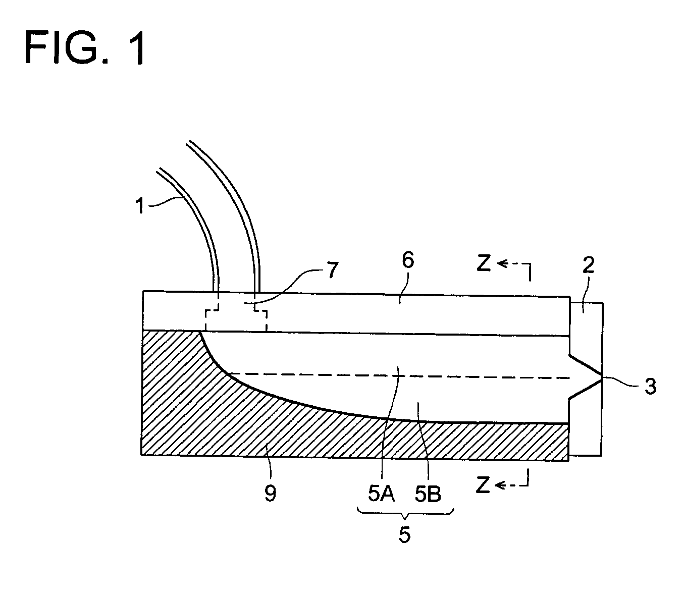
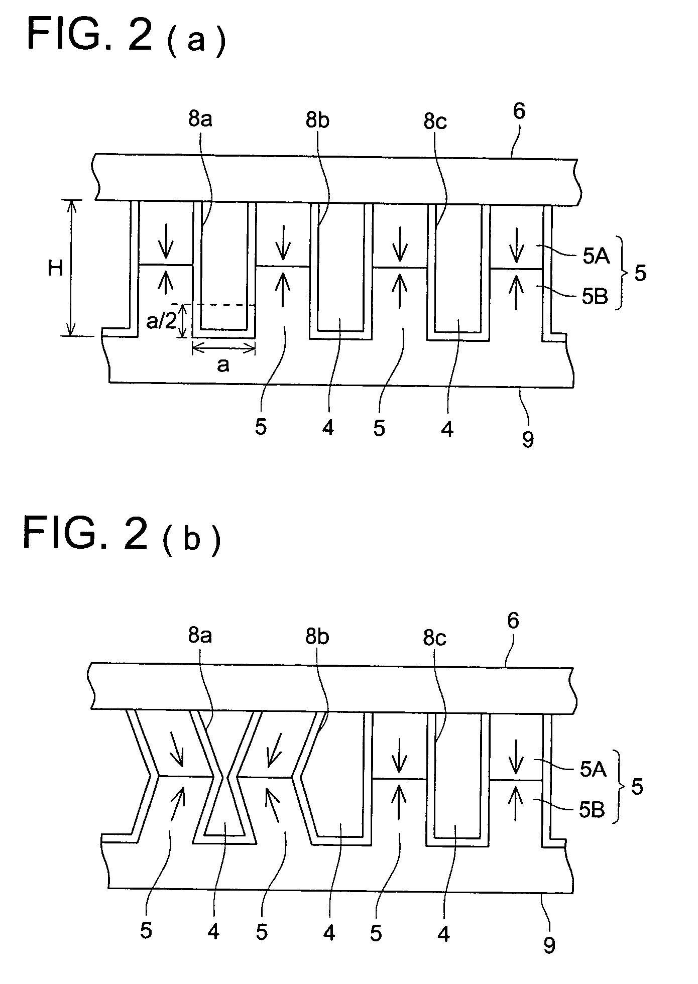
[0084]First, an inkjet recording head was prepared according to the following conditions. As shown in FIGS. 1 to 3, sidewalls were formed by cutting a plurality of grooves on a substrate comprising PZT, and aluminum evaporated electrode was formed on the side surface of each sidewall. A cover plate together with a nozzle forming member the front end of which a nozzle of 25 μmφ is opened was adhered on the top surface of each sidewall by use of an adhesive resulting in constitution of an inkjet recording head. Filler is not mixed into the adhesive.

[0085]Herein, density of an ink channel was 180 dpi (141 μm pitch), each ink channel having ink flow path width of 85 μm and length of 3 mm, and water-based ink (having a specific gravity of 1.06, and a bulk modulus of elasticity of 2.5 GPa) was utilized.

[0086]Total of 4 sets of inkjet recording heads (examples 1–3 and a comparison 1) were prepared with various cross-sectional areas by varying the depth of the ...

Example

Examples 4–6, and Comparison 2

[0092]The inkjet recording heads having 20 μmφ nozzle, ink channel density of 300 dpi (85 μm pitch), ink channel having ink flow path width of 42 μm and length of 2 mm were used. With keeping other conditions same as those of Example 1–3 and Comparison 1, the depth of ink channels were varied to form ink channels with various cross sectional areas as shown in Table 2. Each value of a ratio of compliance (Kcr), CTC, CTE and |CTC+CTE| of each recording head is shown in Table 2.

[0093]Evaluation of each recording head was performed by printing a solid image with a driving pulse of 3 μsec pulse width. Other printing conditions and evaluation criteria were same as those of Example 1–3 and Comparison 1.

[0094]TABLE 2Depth OfImageInk|CTC +Eval-ChannelKcrCTCCTECTE|uationExample125 μm0.452.8%−7.6%4.8%A4Example150 μm0.625.3%−6.6%1.3%A5Example175 μm0.859.9%−6.0%3.9%A6Compari-200 μm1.1317.5%−4.8%12.7%B–Cson 2

Examples 7–9, and Comparison 3

[0095]The inkjet recording he...


PUM


Abstract

An inkjet recording head for ejecting ink, having a plurality of piezoelectric sidewalls to form a plurality of ink channels; a piezoelectric bottom plate; and a plurality of electrodes All of the ink channels are divided into two or more groups of ink channels composed of ink channels between which at least one ink channel is sandwiched;
    • wherein an ink ejection operation is performed successively in a time-sharing mode for each of the group of ink channels, while satisfying the condition of |CTC+CTE|≦10 (%); where a crosstalk between ink channels in one group due to a compliance ratio of the sidewalls to the ink in the ink channel is CTC; and a crosstalk between ink channels in one group due to a leak of electric field caused by electric voltage applied to the electrodes is CTE.

Description

BACKGROUND OF THE INVENTION[0001]The present invention relates to an inkjet recording head, and particularly to an inkjet recording head capable of high speed and stable drive by compensating variation of ink ejection speed from each channel due to crosstalk generated at the time of drive.[0002]Conventional Technology[0003]Various methods have been proposed for an inkjet recording head, and one of these is an inkjet recording head of a shear mode (Patent Literature 1).[0004]FIGS. 1 and 2(a), (b) are drawings to show an example of this inkjet recording head. FIG. 2(a), (b) are partial cross-sectional views taken on line Z—Z in FIG. 1. Number 1 is an ink tube, 2 is a nozzle forming member, 3 is a nozzle, 4 is an ink channel, 5 is a sidewall, 6 is a cover plate, 7 is an ink supply opening, 8 is an electrode and 9 is a substrate. As can be seen from FIG. 1 and FIG. 2(a), ink channels 4 are constituted by sidewalls 5, cover plate 6 and substrate 9, and the ink channels 4 have a flat bott...

Claims


Application Information

Patent Timeline
IPC IPC(8): B41J2/045B41J29/38
CPCB41J2/04525B41J2/04581B41J2/04543B41J2202/10
Inventor TAKEUCHI, YOSHIOTAMURA, AKIHIKOKOMATSU, KATSUAKIASANO, KAZUOKAWABATA, KATUICHI
Owner KONICA MINOLTA INC
Why Eureka
Try Eureka