
Ink jet printer head

Active Publication Date: 2006-07-11
BROTHER KOGYO KK
View PDF10 Cites 18 Cited by
  • Summary
  • Abstract
  • Description
  • Claims
  • Application Information

AI Technical Summary

Benefits of technology

[0030]It is another object of the present invention to provide such an ink jet printer head which can enjoy a small size.
[0031]It is another object of the present invention to provide such an ink jet printer head which can be driven with a low electric voltage and / or can be produced at a low cost.
[0039]According to this mode, when the piezoelectric actuator is fixed to the cavity unit, the external pads of the actuator can be strongly pressed against the partition walls of the cavity unit that are alternate with the pressure chambers, so that the actuator can be reliably fixed to the cavity unit and accordingly the leakage of ink from each pressure chamber can be minimized. In addition, since the pressing force is not directly applied to each pressure chamber as a vacant space, each pressure chamber can be effectively prevented from being deformed and the actuator can be freed of cracks. Therefore, the present ink jet printer head as an end product can enjoy a designed printing quality.
[0047]According to this mode, even if the cavity unit may have a great number of nozzles, the piezoelectric actuator is provided by a plurality of separate actuator portions each of which corresponds to an appropriate number of pressure chambers belonging to a corresponding one of a plurality of groups. Therefore, the active portions of the each of the actuator portions can be accurately positioned relative to the pressure chambers of the corresponding one group. According to this mode, a first distance between the respective one active portions of the two actuator portions that are nearest to the respective one ends thereof is greater than a second distance between each pair of active portions that are adjacent each other in each of the two actuator portions. However, an amount by which the first distance is greater than the second distance is too small. Therefore, if external pads to which flat cables are to be electrically connected, respectively, are provided right above the nearest active portions, respectively, then the first distance is too small for the flat cables to be appropriately connected to the external pads without being interfered with each other. In contrast, according to this mode, the internal pads which electrically connect, in each of the actuator portions, between the individual electrodes and the external pads, can be largely offset from the one end portion of the each actuator portion, and accordingly the external pads can also be largely offset from the respective one ends of the actuator portions. Thus, the flat cables can be easily connected to the external pads without being interfered with each other.
[0054]According to this mode, since the first internal pads are inclined, a length of each first internal pad can be increased, while the distance between the each first internal pad and the first edge line of the common electrode is kept at the first predetermined distance. Therefore, even if, when the common electrode and the first internal pads are formed by, e.g., printing, the contour of common electrode and / or first internal pads may be deformed and the area of the same may be somewhat increased or decreased from a nominal value, no electric current leaks between two first internal pads next to each other, upon application of electric voltage to the same, because a distance greater than a certain distance is provided. Thus, only a desired active portion or portions of the piezoelectric actuator corresponding to a desired pressure chamber or chambers can be assuredly operated, which leads to exhibiting a good printing quality of the printer head. Consequently the short sides of the piezoelectric actuator can be decreased and accordingly the printer head can be reduced in size.

Problems solved by technology

Thus, ink may leak from one of the pressure chambers into another pressure chamber.
Thus, both the piezoelectric actuator and the cavity unit cannot be downsized.
If the respective end portions of the individual electrodes that are extended in the respective outward directions away from the corresponding pressure chambers, are shortened to solve the above-identified problems, then other problems arise that the size of each of the active portions is adversely limited and that since an electrically conductive material connecting between the individual electrodes and the individual surface electrodes is located too near to the active portions, the operation of each of the active portions is adversely limited.
Thus, cracks may occur to the piezoelectric sheets, or a sufficiently strong pressing force may not be applied to the piezoelectric actuator, or may not be uniformly distributed over the same.
These problems may lead to a defect of the printer head that the piezoelectric actuator and the cavity unit are not sufficiently strongly bonded to each other.
Furthermore, since the pressing force applied to the piezoelectric actuator may change the original shape of each pressure chamber of the cavity unit, i.e., may change designed plan-view shape and / or cross-sectional area of the same, the printer head may not be able to enjoy its designed printing quality.
However, because the accuracy of production of piezoelectric actuators and the temperature at which piezoelectric actuators are fired are not sufficiently constant, it is difficult for each final product to have the regular interval, at which the individual electrodes are provided, that is equal to the regular interval at which the pressure chambers are provided.
This leads to lowering the yield of final products.
However, if the piezoelectric actuator is divided into the plurality of actuator units that are arranged in series in the direction parallel to the array of nozzles, and two flat cables are bonded to the respective top surfaces of the actuator units, another problem occurs.
Therefore, when the above-indicated flat cables as they are bonded to the actuator units, respectively, such that the connection electrodes of the flat cables are electrically connected to the external connection electrodes of the actuator units, respective end portions of the flat cables interfere with each other, so that the strength of bonding of the flat cables with the actuator units is insufficiently small and the small bonding strength may lead to a problem such as failure of electric conduction.
When the various electrodes, such as the proper and dummy individual electrodes and the proper and dummy common electrodes, are formed by screen printing, such a problem occurs that the area of each electrode may change from a nominal value, i.e., increase or decrease, because, e.g., the contour of the each electrode is deformed when the screen is removed.
If this problem leads to excessively decreasing a distance between two electrodes next to each other, then another problem occurs that when an electric voltage is applied to the electrodes, an electric current may leak between two electrodes next to each other, and an undesired active portion different from the desired active portion may be operated.
Thus, the amount of electrically conductive material (e.g., electrically conductive paste), such as silver-palladium-based material, needed to form each common electrode is increased, and accordingly the cost of production of the piezoelectric actuator is increased.
Therefore, the difficulty of the above-identified problems increases as the number of the arrays of the active portions increases.

Method used


Image

  • Ink jet printer head
  • Ink jet printer head
  • Ink jet printer head

Examples


Embodiment Construction

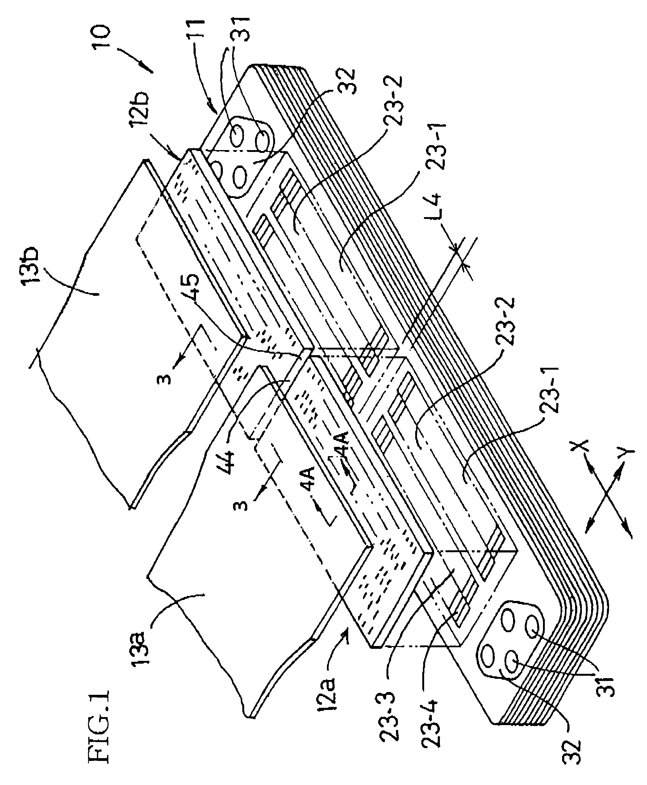
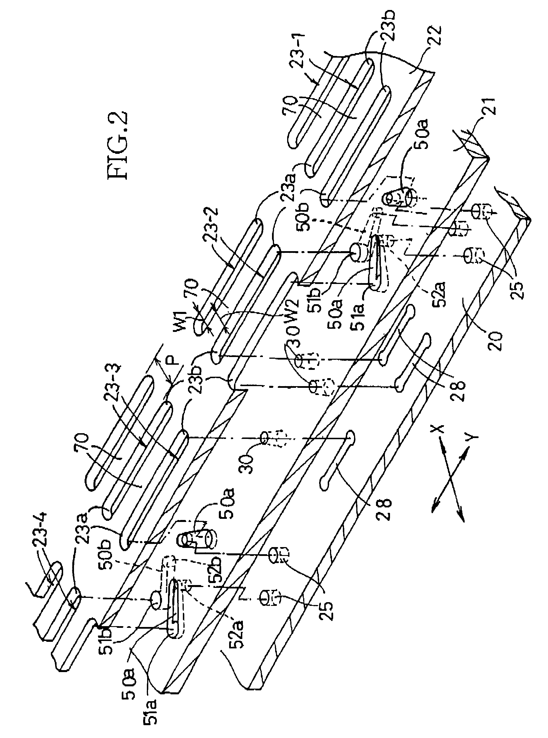
[0086]Hereinafter, there will be described preferred embodiments of the present invention by reference to the drawings. FIG. 1 shows a cavity unit 11 and a piezoelectric actuator 12 (i.e., two actuator units 12a, 12b) of a piezoelectric-type ink jet printer head 10 to which the present invention is applied; and FIG. 2 shows three sheet members each as part of the cavity unit 11, i.e., a base sheet 22, and a third and a second spacer sheet 21, 20 that are adjacent a lower surface of the base sheet 22. In FIG. 1, the sheet-stacked-type piezoelectric actuator 12 (i.e., the two actuator units 12a, 12b) is bonded to an upper surface of the metal-sheet-based cavity unit 11, and a flexible flat cable 13 (i.e., two cable units 13a, 13b; also see FIGS. 3 and 4A) as a sort of cable member is stacked on, and bonded to, an upper surface of the piezoelectric actuator 12. More specifically described, the two cable units 13a, 13b are bonded to the respective upper surfaces of the two actuator unit...


PUM


Abstract

An ink jet printer head includes a cavity unit and a piezoelectric actuator that is bonded to the cavity unit. The piezoelectric actuator includes a top sheet on which external pads are formed in arrays, at an appropriate pitch in each array, in a direction parallel to a direction in which nozzles are formed in arrays in the cavity unit. The external pads are electrically connected to respective individual electrodes via respective internal leads, and also to a flat cable. Each of the external pads is formed at a position right above a partition wall that separates two pressure chambers from each other in the cavity unit. Therefore, when the piezoelectric actuator is bonded to the cavity unit, the external pads of the actuator can be strongly pressed against the partition walls of the cavity unit, so that the actuator can be strongly bonded to the cavity unit and the amount of leakage of ink from the pressure chambers can be minimized. In addition, since the pressing force is not directly applied to the pressure chambers each as a vacant space, the pressure chambers can be prevented from being deformed and the piezoelectric actuator can be prevented from being cracked.

Description

BACKGROUND OF THE INVENTION[0001]1. Field of the Invention[0002]The present invention relates to an ink jet printer head and particularly to such an ink jet printer head which includes a cavity unit having a plurality of pressure chambers, and a piezoelectric actuator fixed to the cavity unit.[0003]2. Discussion of Related Art[0004]Patent Document 1 (i.e., Japanese Patent Publication Document No. 2001-246744 or its corresponding U.S. Patent Publication Document No. 2001-020968), Patent Document 2 (i.e., Japanese Patent Publication Document No. 2002-019102 or its corresponding U.S. Patent Publication Document No. 2002-003560), Patent Document 3 (i.e., Japanese Patent Publication Document No. 2002-059547 or its corresponding U.S. Patent Publication Document No. 2002-024567), or Patent Document 4 (i.e., Japanese Patent Publication Document No. 2002-036544 or its corresponding U.S. Patent Publication Document No. 2002-003560) discloses an on-demand ink jet printer head. The disclosed pr...

Claims


Application Information

Patent Timeline
IPC IPC(8): B41J2/045B41J2/14B41J2/16
CPCB41J2/14209B41J2002/14217B41J2002/14225B41J2002/14306B41J2202/20B41J2002/14491B41J2202/11B41J2202/18B41J2002/14419
Inventor ISONO, JUNITO, ATSUSHI
Owner BROTHER KOGYO KK
Learn More