Laminate-type positive temperature coefficient thermistor

a positive temperature coefficient and thermistor technology, applied in the direction of positive temperature coefficient thermistors, resistor details, adjustable resistors, etc., can solve problems such as breakage in the center of laminates, and achieve the effect of improving the resistance to voltage properties

Active Publication Date: 2006-07-11
MURATA MFG CO LTD
View PDF16 Cites 20 Cited by
  • Summary
  • Abstract
  • Description
  • Claims
  • Application Information

AI Technical Summary

Benefits of technology

[0008]In order to overcome the problems described above, preferred embodiments of the present invention provide a laminate-type posit...

Problems solved by technology

Probably, the heat-dissolution causes the abov...

Method used


Image

  • Laminate-type positive temperature coefficient thermistor
  • Laminate-type positive temperature coefficient thermistor
  • Laminate-type positive temperature coefficient thermistor

Examples


example 1

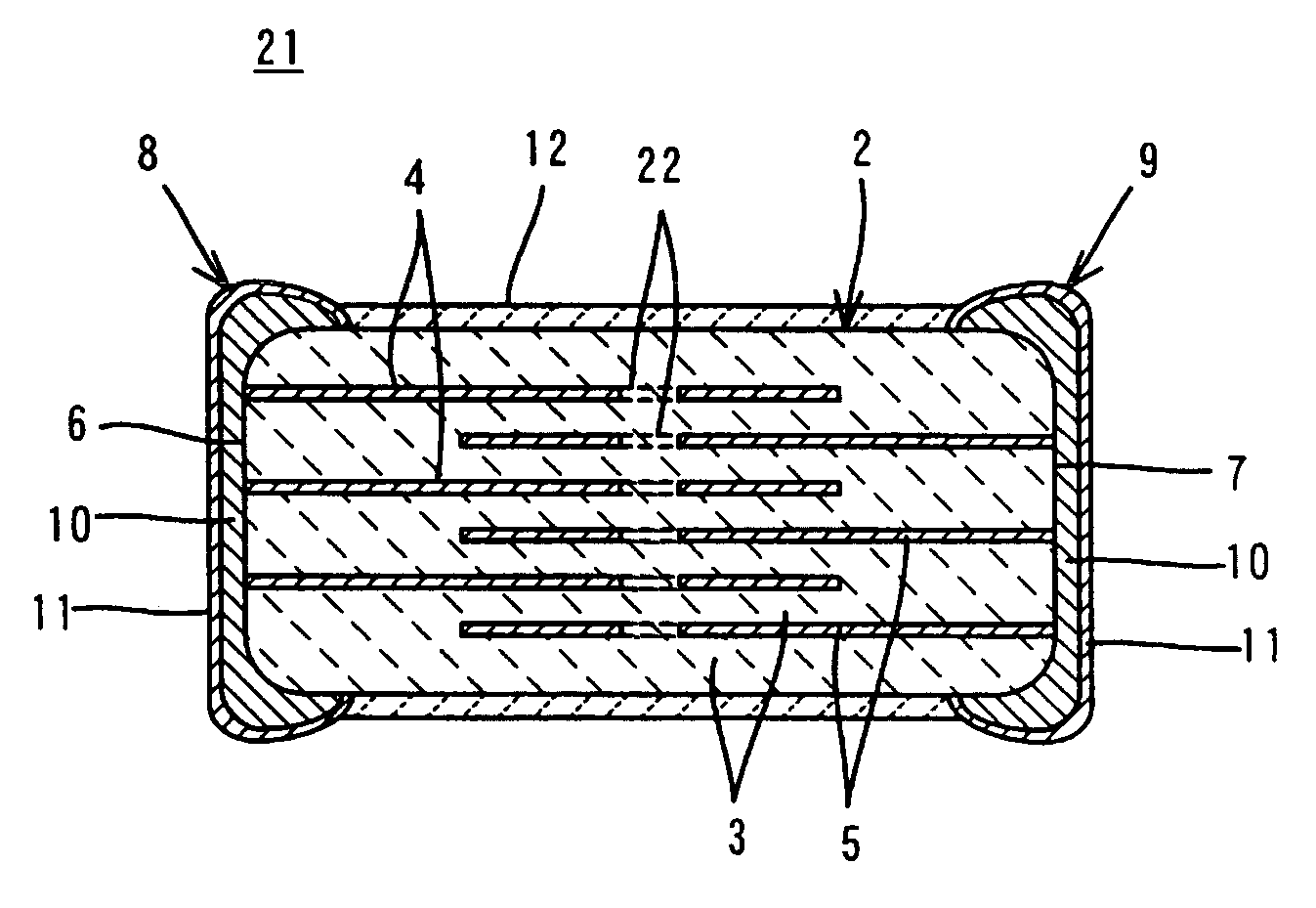
[0076]In Example 1, an example of the first preferred embodiment described with reference to the FIGS. 1, 2A, and 2B is evaluated.

[0077]First, powders of BaCO3, TiO2 and Sm2O3 were prepared. These powdery raw materials were mixed so as to form (Ba0.9998Sm0.0002)TiO3.

[0078]Subsequently, refined water was added to the produced mixed powder, crushed with stirring for 10 hours, dried, and calcined at a temperature of 1000° C. for 2 hours.

[0079]Thereafter, to the calcined powder, an organic binder, a dispersant, and water were added and mixed with zirconia balls for several hours. The produced slurry was formed into a green sheet with a thickness of about 30 μm.

[0080]Subsequently, electroconductive paste including nickel as an electroconductive component was applied onto the green sheet by screen-printing, and was dried. Thus, the green sheet having an electroconductive paste film for forming the internal electrode was prepared. A substantially circular perforation with a diameter of abo...

example 2

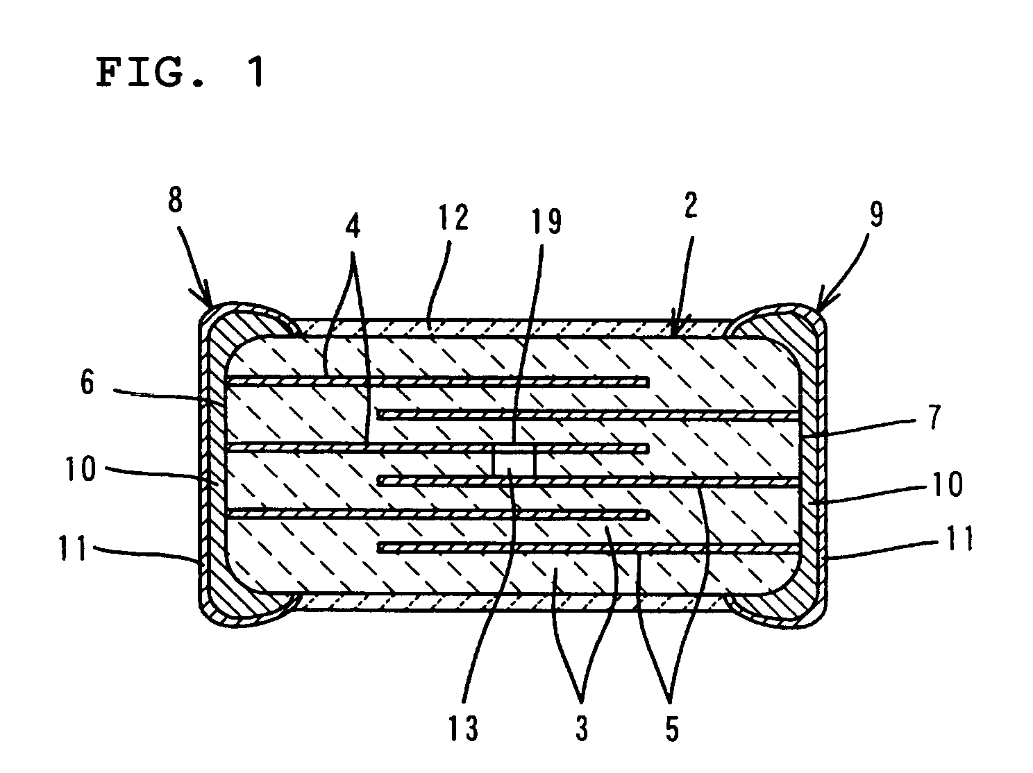
[0092]In Example 2, examples of the second preferred embodiment described with reference to FIG. 3 and FIGS. 4A and 4B are evaluated.

[0093]Green sheets were formed in the same manner and conditions as those in Example 1.

[0094]Subsequently, electroconductive paste including nickel as an electroconductive component was applied onto the green sheets by screen-printing to form electroconductive paste films. In this case, as an area corresponding to the area 27 having no electroconductive paste applied thereon as shown in FIGS. 4A and 4B, formed in the approximate center of the portion of the laminate where the internal electrodes overlapped, a substantially circular area with a diameter of about 0.1 mm was formed for Sample 11, a substantially circular area with a diameter of about 0.2 mm was formed for Sample 12, and a substantially circular area with a diameter of about 0.5 mm was formed for Sample 14. For Sample 14, an area having no electroconductive paste applied thereon was not fo...

example 3

[0103]In Example 3, the third preferred embodiment described with reference to FIG. 5 and FIGS. 6A and 6B is evaluated.

[0104]Green sheets were formed in the same manner and conditions as those in Example 1.

[0105]Subsequently, electroconductive paste including nickel as an electroconductive component was applied onto the green sheets by screen-printing to form electroconductive paste films. In this case, green sheets having the electroconductive paste film 35 evenly formed thereon, as shown in FIG. 6A, were produced, and also, green sheets each having an area (about 0.1 mm in width×about 1.7 mm in length) not having the electroconductive paste applied thereon in the approximate center of the portion of the laminate where the internal electrodes overlapped each other, as shown in FIG. 6B, were produced.

[0106]Subsequently, the plural green sheets having the electroconductive paste films formed as shown in FIG. 6A, and the plural green sheets 34 having the electroconductive paste films ...


PUM


Abstract

A positive temperature coefficient thermistor has a non-heating portion which is not heated when a voltage is applied between first and second internal electrodes. The non-heating portion is provided in the approximate center of the positive temperature coefficient thermistor and is arranged to extend along a direction that is substantially perpendicular to a lamination direction of the positive temperature coefficient thermistor. The non-heating portion is arranged at least in the approximate center in the lamination direction of the portion of the laminate where the first and the second internal electrodes are arranged. Thus, a hot spot is reliably prevented from occurring inside the laminate when voltage is applied. As a result, the withstand voltage property is greatly improved. The non-heating portion may include a cavity provided in at least one thermistor layer or an opening or cut portion provided in the internal electrode.

Description

BACKGROUND OF THE INVENTION[0001]1. Field of the Invention[0002]The present invention relates to a positive temperature coefficient thermistor and more particularly to a laminate-type positive temperature coefficient thermistor having a greatly improved withstand voltage property.[0003]2. Description of the Related Art[0004]Generally, laminate-type positive temperature coefficient thermistors have the following structure (for example, see Japanese Unexamined Patent Application Publication No. 5-47508).[0005]In particular, a laminate-type positive temperature coefficient thermistor includes a substantially rectangular laminate with a positive resistance-temperature coefficient. The laminate has a plurality of laminated thermistor layers, and first and second external electrodes formed on the outer surface, that is, on the first and second opposed end surfaces of the laminate.[0006]Moreover, a plurality of first and second internal electrodes are uniformly formed on predetermined inte...

Claims


Application Information

Patent Timeline
IPC IPC(8): H01C7/10H01C7/02
CPCH01C7/021H01C7/02
Inventor MIHARA, KENJIRONIIMI, HIDEAKI
Owner MURATA MFG CO LTD
Why Eureka
Try Eureka