
Lead-defined and shaped magnetic sensor

a magnetic sensor and lead-defined technology, applied in the field of magnetic transducers, can solve the problems of limited success of this “brute force” approach, consume the total gap tolerance of the combined sensor, and little margin for insulating, so as to improve magnetic stability, narrow track width, and narrow track width

Inactive Publication Date: 2006-07-11
HITACHI GLOBAL STORAGE TECH NETHERLANDS BV
View PDF16 Cites 17 Cited by
  • Summary
  • Abstract
  • Description
  • Claims
  • Application Information

AI Technical Summary

Problems solved by technology

There have been some efforts to stabilize very narrow sensor elements by using increasingly thick hard bias structures, but there has been only limited success with this “brute force” approach.
One problem with this approach is that it consumes the total gap tolerance for the combined sensor / lead structure leaving little margin for insulating gap layers to provide edge coverage and for electrical insulation from the shields.
Consequently these designs require complex mask steps and decrease yield through losses due to shield shorts.

Method used

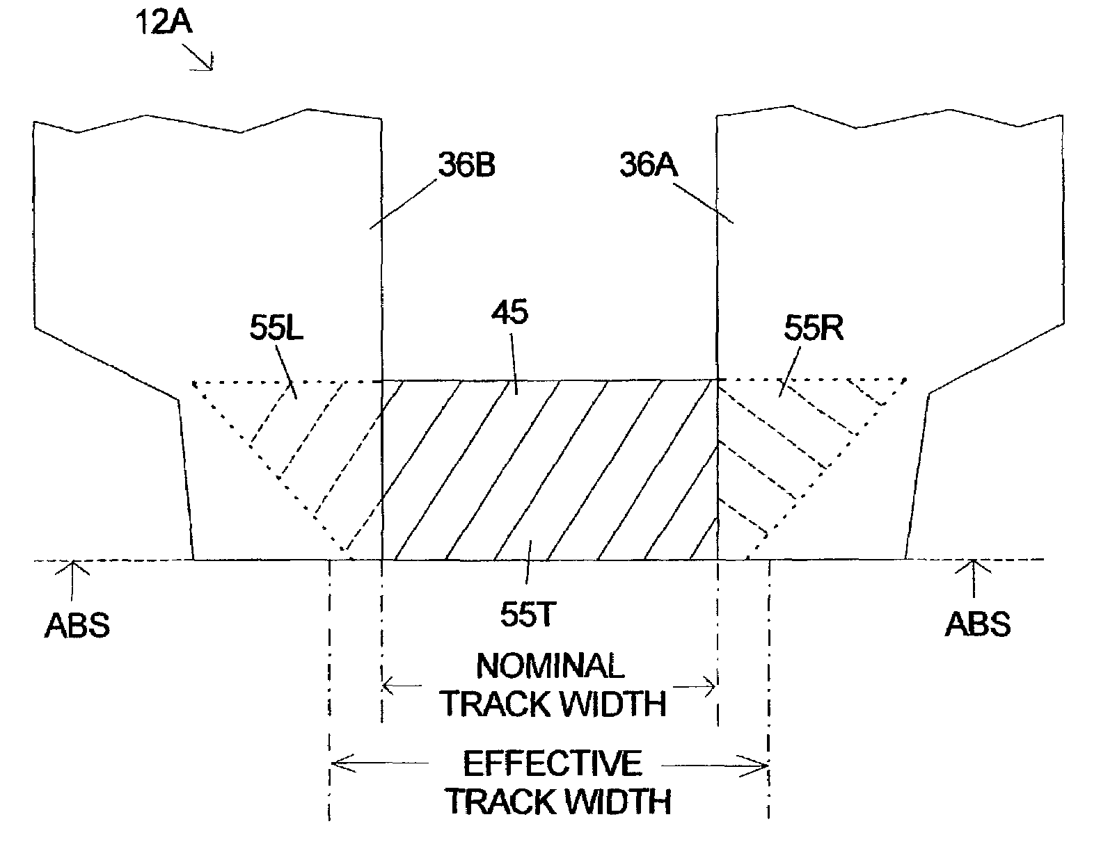

Image

  • Lead-defined and shaped magnetic sensor
  • Lead-defined and shaped magnetic sensor
  • Lead-defined and shaped magnetic sensor

Examples


Embodiment Construction

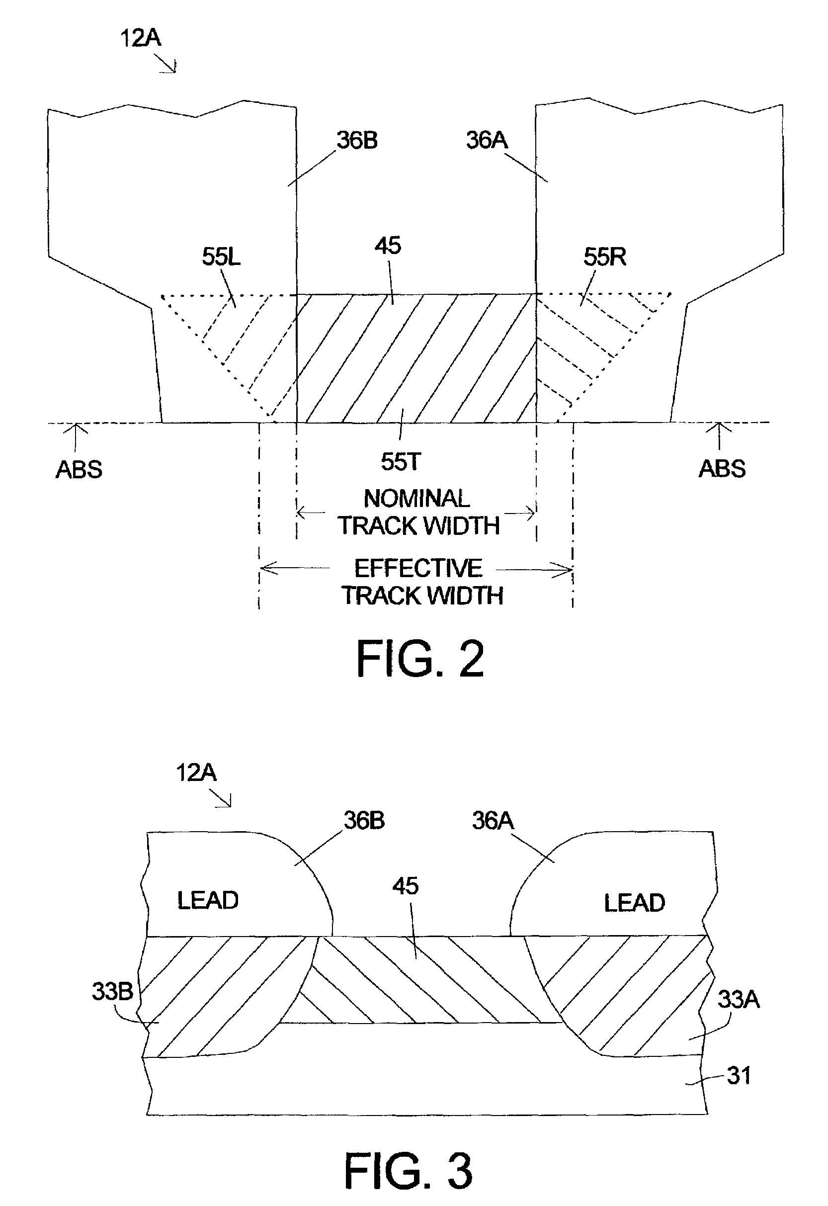
[0016]The relative sizes / thickness of the components are according to prior art principles except where noted below. The hatching lines in the drawings are not intended to represent the material composition of a structure, but are used only to distinguish structures and aid in the explanation of the process of making the write element.

[0017]GMR / MR sensor elements with rectangular shapes have an inherent tendency to break up into multiple magnetic domain states due to effects of energy minimization associated with closure domain formation. In general, these closure domains are associated with the junction of three domain walls where the angle between the walls is 120 degrees. This angle is known to be associated with minimal wall energy and may be thought of as a critical angle for energy minimization. An MR stripe with a trapezoidal shape can be formed with an angle of 120 degrees. There are other shapes which have similar properties such as a hexagon, a “race-track”, and a half-rac...


PUM

PropertyMeasurementUnit
anglesaaaaaaaaaa
angleaaaaaaaaaa
magnetoresistiveaaaaaaaaaa

Abstract

A magnetic recording transducer, useful in a magnetic data storage device, having a read element with improved magnetic stability and a narrow track width is described. An MR stripe according to the invention has a magnetic-stability inducing (MSI) shape selected from an essentially trapezoidal shape, an essentially hexagonal shape, an essentially race-track shape, and an essentially half race track shape. These MSI shapes are oriented in a plane perpendicular to the air-bearing surface (ABS). The MSI shapes are used to encourage the formation of a single magnetic domain state with magnetization direction parallel to the ABS in the absence of a magnetic bias. In one embodiment according to the invention the sensor structure is overlaid on the sides of the top surface with layers of electrically conductive material (overlaid leads) to define an approximately rectangular active region of the larger MSI shape. A sensor structure according to the invention with overlaid leads will have a narrower track width with improved magnetic stability than a sensor which has a comparable volume of magnetoresistive material in a rectangular MR stripe. In another embodiment of the invention the sensor structure has edge-butt leads that make contact at the outer edges of the sensor without substantially overlaying the top surface.

Description

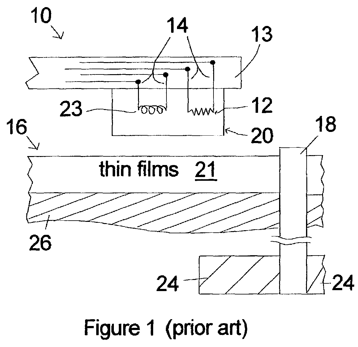
FIELD OF THE INVENTIONThe invention relates to the field of magnetic transducers (heads) having MR or GMR sensor elements and more particularly to the structure of the MR / GMR sensor and the leads connected to the sensor.BACKGROUND OF THE INVENTION[0001]A typical prior art head and disk system 10 is illustrated in FIG. 1. In operation the magnetic transducer 20 is supported by the suspension 13 as it flies above the disk 16. The magnetic transducer 20, usually called a “head” or “slider,” is composed of elements that perform the task of writing magnetic transitions (the write element 23) and reading the magnetic transitions (the read element 12). The electrical signals to and from the read and write head elements 12, 23 travel along conductive paths (leads) 14 which are attached to or embedded in the suspension 13. The magnetic transducer 20 is positioned over points at varying radial distances from the center of the disk 16 to read and write circular tracks (not shown). The disk 16 ...

Claims


Application Information

Patent Timeline
Patent Type & Authority Patents(United States)
IPC IPC(8): G11B5/39G11B5/31
CPCB82Y10/00B82Y25/00G11B5/3909G11B5/398G11B5/3903G11B5/313Y10T29/49052G11B2005/3996
Inventor PARKER, MICHAEL ANDREW
Owner HITACHI GLOBAL STORAGE TECH NETHERLANDS BV
Learn More