Brake rotor attachment assembly that promotes in plane uniform torque transfer distribution

a technology of torque transfer and rotor, which is applied in the field of brake assembly, can solve the problems of thermal distortion of the rotor, high cost and time consumption, and the drawbacks of the hat rotor, and achieve the effects of promoting uniform torque transfer, reducing bending stress, and reducing bending stress

Inactive Publication Date: 2006-07-18
PERFORMANCE FRICTION
View PDF45 Cites 18 Cited by
  • Summary
  • Abstract
  • Description
  • Claims
  • Application Information

AI Technical Summary

Benefits of technology

[0023]An aspect of the invention also provides a spring at the fastener connection to minimize or prevent rattling of the rotor assembly during use.
[0024]An additional aspect of the invention provides a rotor with an attachment flange having tabs that are clamped to the hat portion, which can eliminate fatigue fractures and / or stress concentrations typically associated with perforated attachment flanges, to enhance performance and durability.
[0025]Another aspect of the invention provides a hat piece for attachment to the rotor that is designed to receive less stresses from the fastener assembly so that material with lower hardness can be used, if desired.
[0026]The invention is directed to a brake assembly comprising a rotor having a braking surface and an attachment flange; a hat portion having a mounting surface for attachment to a vehicle wheel; and a fastener assembly that couples the hat portion to the attachment flange. The fastener assembly includes a plurality of bobbins and fasteners. The fasteners extend through the hat portion and each bobbin to clamp the attachment flange between the hat portion and the bobbin. If desired, a spring can be disposed between the attachment flange and bobbin. The fastening assembly transfers torque from the braking surface to the hat portion in a common plane to prevent twisting. A crush zone can also be provided in association with the fastener assembly to promote uniform torque transfer distribution from the attachment flange to the hat portion.

Problems solved by technology

A significant drawback, however, is that the assembly is constrained at the hub, which causes thermal distortion of the rotor.
Such thermal distortion can damage the rotor and when the rotor is damaged or worn, entire integrated assembly must be replaced.
This is expensive and time consuming.
Hat rotors, however, also have some drawbacks.
Rotor run-out causes excessive and uneven wear in the rotor braking surfaces and in brake pads which contact the rotor braking surfaces.
Rotor run-out also increases thermal distortion of the brake rotor.
The thermal distortion results in thermal judder, noise, and vibrations during braking, as well as causing irregular braking pulsations.
This can be a significant problem as it is very difficult to achieve perfect machining.
Another deficiency with hat rotor hub assemblies results from the manner in which a hat rotor and a wheel are mounted together on the hub.
However, if the wheel lug nuts are not evenly tightened, the uneven forces acting on the hub may result in the distortion of the hub.
Additionally, if the wheel rim has been improperly manufactured, the wheel rim might impose a distortion on the hub as the lug nuts are tightened.
This induces stresses in the rotor.
During braking, the rotor in such an assembly is subjected to high frictional forces that generate heat in the rotor causing thermal expansion / distortion, temperature variation across the face of the rotor, and heat transfer to the adjacent components including the hub and the bearings.
Thermal expansion of the rotor is very limited because of the integral connection between the rotor and the hub.
This creates thermal coning in the rotor surface and a large thermal gradient, which will induce high thermal stress leading to thermal cracking.
The high thermal gradient generated during braking and the effects of the thermal expansion and distortion can cause vibration and thermal judder across the brake surfaces, resulting in a rough or irregular braking pulsations.
The high thermal stress and thermal distortion also reduce the life and performance of the rotor and increase maintenance costs.
This creates twisting in the areas adjacent the fastener, which can create fatigue leading to cracking and breaking.
The perforated flange tends to become fatigued because the material of the rotor, cast iron for example, weakens at high temperatures leading to fatigue fractures.
This also creates problems with run-out, as discussed above, along with premature fracture of components in the connection.
Torque transfer also tends to be non-uniform through the perforated flange, especially in a floating design, as the machining tolerance at each aperture causes certain connections to receive more torque than other connections.
This creates high stresses at individual apertures and can cause the attachment flange to crack or to have portions break off.
The two-piece hat rotor assemblies discussed above also have drawbacks associated with the hat portion, which typically has slots that match with the perforations in the rotor attachment flange.
This twisting causes the edges of the bobbin, which are typically square to match the slot, to gouge the sides of the slots, thus damaging the slotted piece.
In summary, prior art brake rotors have suffered from problems associated with wear and material fatigue due to stresses induced during the braking process, particularly bending stresses caused during torque transfer and non-uniform transfer of torque caused by machining tolerances.

Method used


Image

  • Brake rotor attachment assembly that promotes in plane uniform torque transfer distribution
  • Brake rotor attachment assembly that promotes in plane uniform torque transfer distribution
  • Brake rotor attachment assembly that promotes in plane uniform torque transfer distribution

Examples


Embodiment Construction

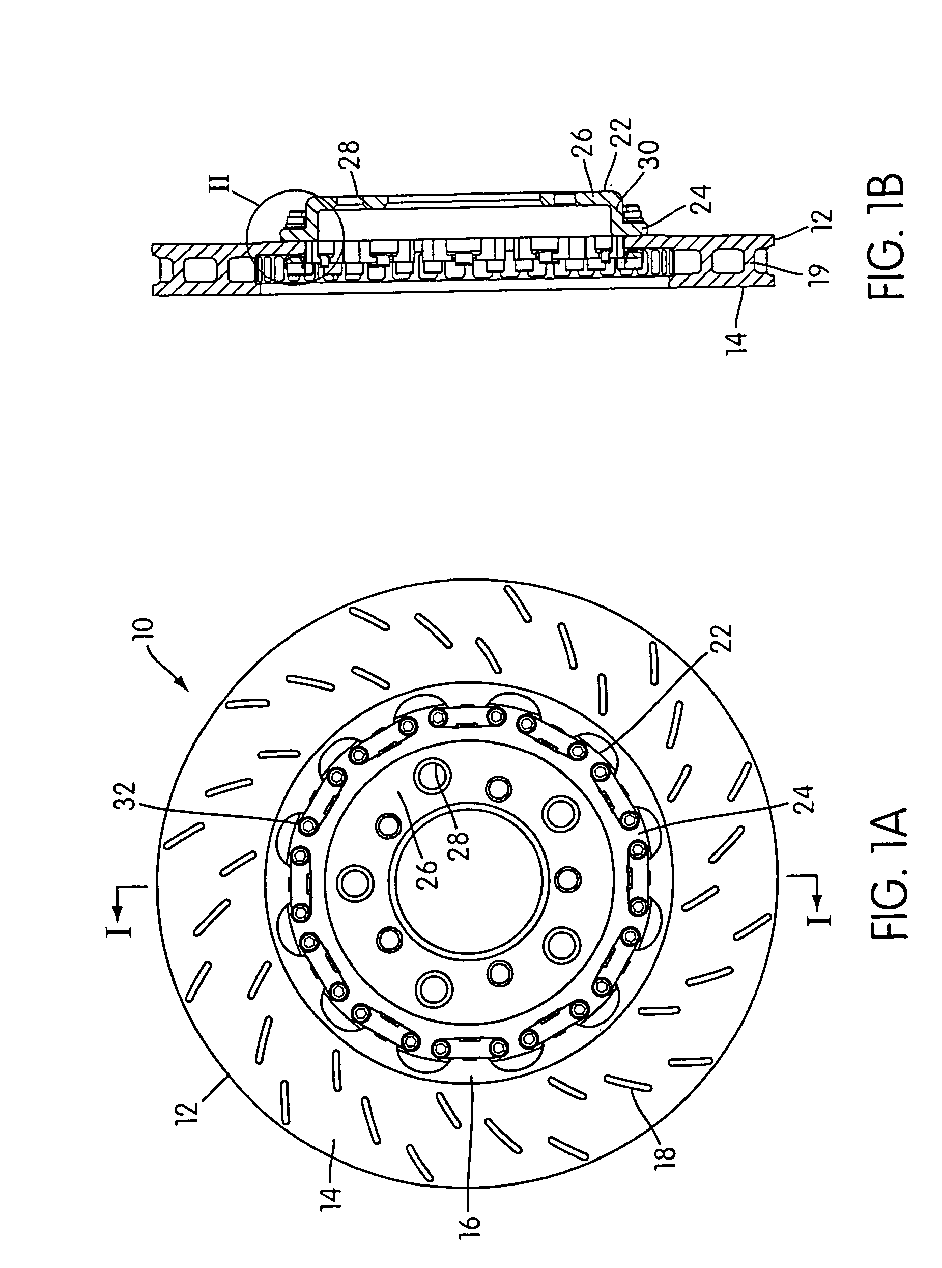
[0068]The brake assembly 10 seen in FIG. 1A is preferred for use on vehicles, including automobiles, racing vehicles, trucks, heavy duty trucks, motorcycles and the like. The vehicles suitable for use with this invention can include those vehicles having a gross vehicle weight of less than about 5,000 pounds, a gross vehicle weight of about 5,000 pounds to 12,000 pounds, and a gross vehicle weight of more than about 12,000 pounds, for example 30,000 pounds. However, the inventive concepts discussed herein can be used in any type of application that uses rotary brakes, including automotive, other types of motorized vehicles, or railcars.

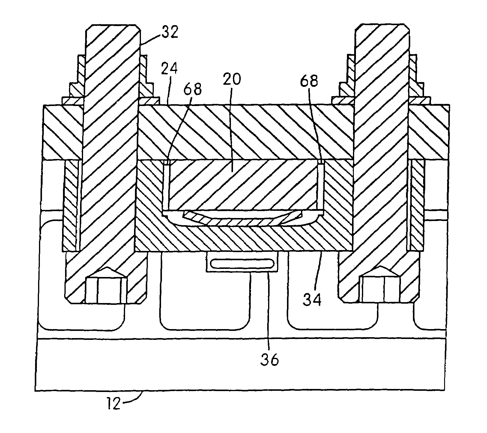
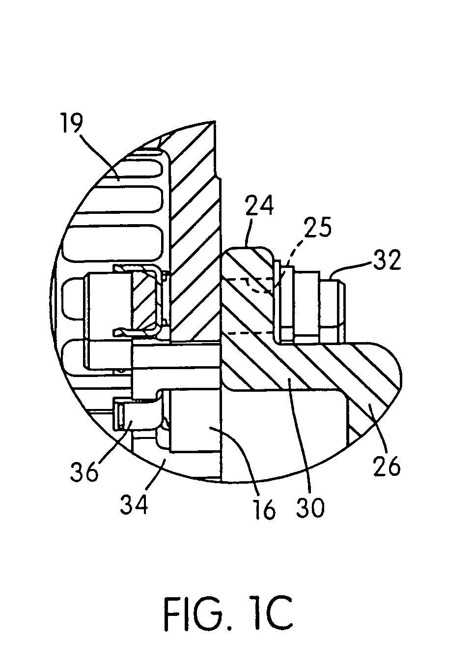
[0069]FIG. 1A shows a rotor disc 12 formed as an annular plate having a braking surface 14 and an attachment flange 16. As known, the braking surface 14 preferably carries a high friction material or can be specially treated. The braking surface 14, as seen, has a plurality of shallow grooves 18 formed therein. These grooves 18 enhance braking, but ar...


PUM


Abstract

A brake assembly for use on vehicles includes a rotor and a wheel mount, formed as a hat portion, fastened to the rotor with a bobbin assembly. The rotor has a flange formed as a series of spaced tabs, and the bobbin assembly is bolted to the hat portion with the rotor flange clamped therebetween. A spring clip can be used with the bobbin to accommodate thermal expansion of the rotor and eliminate rotor rattling. The bobbin has a binocular shape that receives a pair of bolts. A crush zone can be provided between the rotor and the bobbin yields to accommodate machining tolerances of the rotor and promote uniform torque transfer distribution to the hub. Torque is transferred from the brake rotor to the hat portion in a common plane to prevent twisting in the fastener connection.

Description

[0001]This application is a divisional application of U.S. Ser. No. 10 / 404,534 filed Apr. 2, 2003, which claims priority from provisional application No. 60 / 440,611 filed Jan. 17, 2003, and No. 60 / 453,519 filed Mar. 12, 2003. The contents of each of these applications are hereby incorporated herein by reference.BACKGROUND OF THE INVENTION[0002]1. Field of the Invention[0003]The invention relates to brake assemblies, especially vehicular brakes including brake rotors attached to wheel hubs.[0004]2. Description of Related Art[0005]One type of common prior art brake design for vehicles is a two piece hat rotor and hub in which a hat rotor that carries the braking surface is detachably connected to a wheel hub. Another common type of brake design is an integrated one-piece rotor and hub assembly.[0006]Integrated one-piece rotor and hub assemblies have the advantage that no fasteners are required between the rotor and the hub. As a result, the integrated assemblies do not face problems a...

Claims


Application Information

Patent Timeline
Patent Type & Authority Patents(United States)
IPC IPC(8): F16D65/10F16D65/12
CPCF16D65/123F16D2065/1396F16D2065/1392F16D2065/1376
Inventor BURGOON, DONALD L.QIAN, WENQIOAKLEY, JASON C.
Owner PERFORMANCE FRICTION
Why Eureka
Try Eureka