Micro-optics concentrator for solar power satellites

Inactive Publication Date: 2006-07-18
RABINOWITZ MARIO
View PDF11 Cites 63 Cited by
  • Summary
  • Abstract
  • Description
  • Claims
  • Application Information

AI Technical Summary

Benefits of technology

[0034]This invention provides a means for reducing the cost of solar energy derived from solar power satellites by utilization of a micro-optics solar concentrator that is both lightweight and low cost. The technology disclosed in the instant invention makes available large quantities of power that can be transmitted from space to the Earth from either man-launched orbiting satellites or the moon. In the va

Problems solved by technology

A limiting factor in the utilization of solar energy is the

Method used


Image

  • Micro-optics concentrator for solar power satellites
  • Micro-optics concentrator for solar power satellites
  • Micro-optics concentrator for solar power satellites

Examples


Embodiment Construction

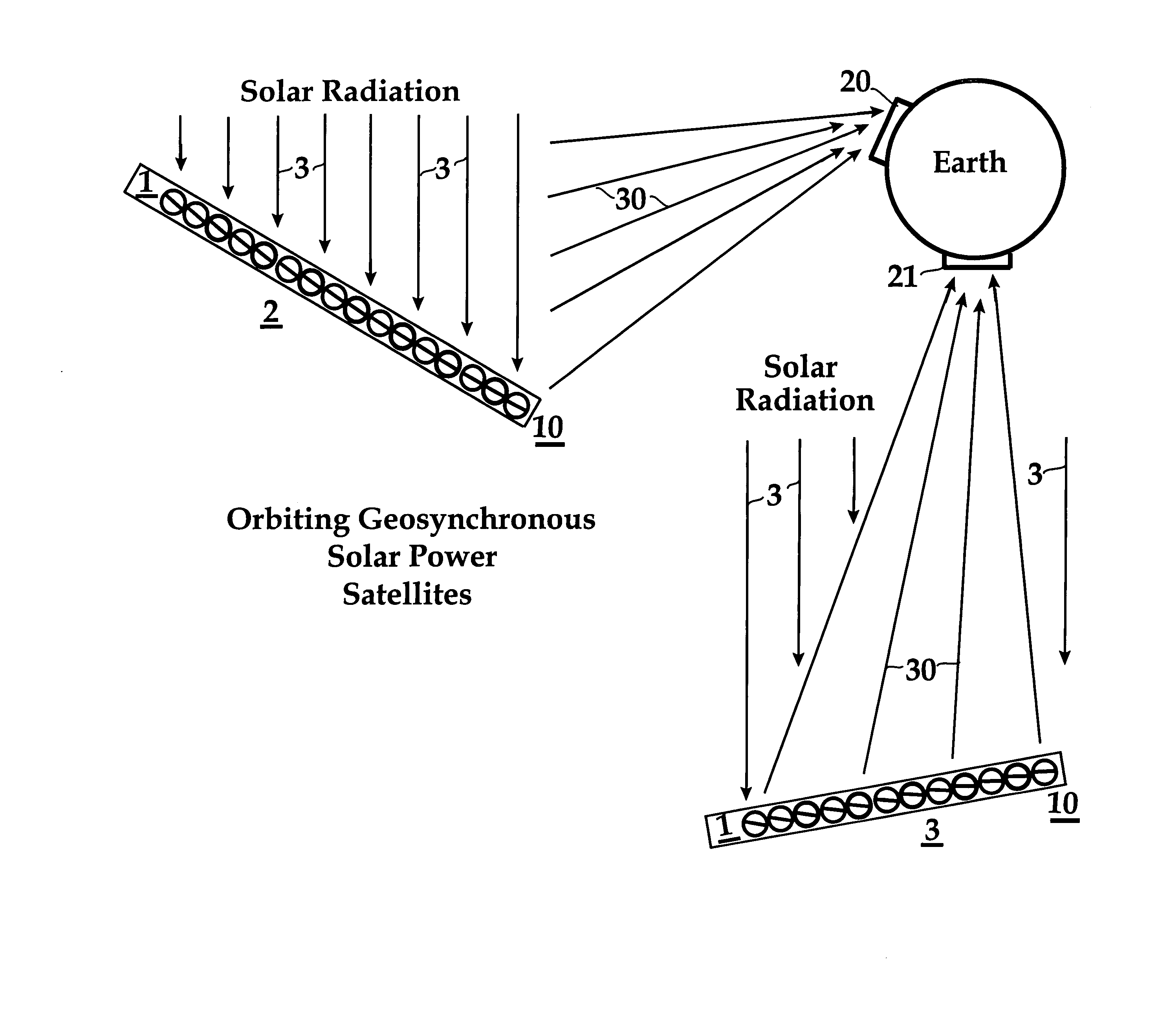
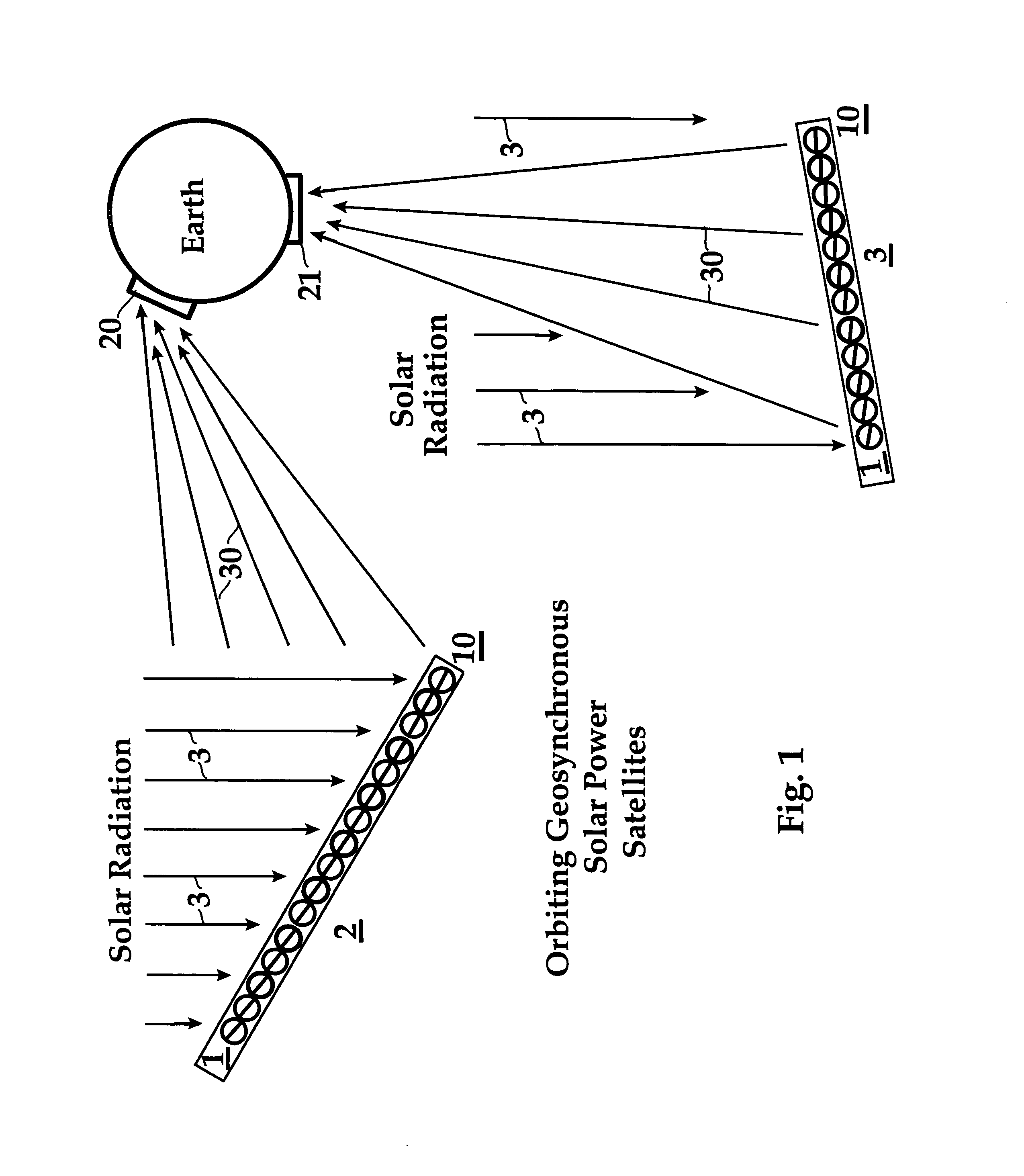
[0063]FIG. 1 is a perspective view (not drawn to scale) showing a solar power reflecting satellite 2 which orbits the Earth, and is equipped with a micro-optics solar concentrator 10 containing rotatable elements 1 to intercept solar radiation 3 and directly reflect the solar radiation as a focussed beam 30 to a receiving station 20 on the Earth. The rotatable elements 1 are balls or cylinders that are preferably less than 1 mm in radius, and are transparent in the upper semi-sphere or semi-cylinder. The rotatable elements 1 containing micro-mirrors as described in conjunction with FIGS. 5a to 5d are aligned in part by grid lines of wire electrodes 6t as described in conjunction with FIGS. 7a and 7b. A second orbiting solar power reflecting satellite 3 is similarly equipped with a micro-optics solar concentrator 10 to intercept solar radiation 3 and directly reflect this solar radiation 3 as a focussed beam 30 to another receiving station 21 (or the same station 20) on the Earth. Th...


PUM


Abstract

There is an increasingly intense need to harness solar energy due to an ever growing shortage of conventional energy sources, The instant invention is concerned with method and apparatus for solar concentrator micro-mirrors on solar power satellites and the moon to focus and reflect large quantities of solar energy. Method and apparatus are taught for directly reflecting solar energy to the Earth; reflecting solar energy to a microwave converter in space which transmits microwave energy to the Earth; and reflecting solar energy to a laser radiation converter which beams laser radiation to the Earth. The concentrated energy received at the Earth may be converted directly to electricity or indirectly by thermo-mechanical means. The advantages and disadvantages of the different means of sending such concentrated energy to the Earth are discussed. A particularly important objective of this invention is the focussing of sunlight for solar power conversion and production. The instant invention can contribute to the goal of achieving environmentally clean solar energy on a large enough scale to be competitive with conventional energy sources.

Description

INCORPORATION BY REFERENCE[0001]The following U.S. patents, allowed patent applications, and pending patent applications are fully incorporated herein by reference:[0002]1. U.S. Pat. No. 6,843,573 by Mario Rabinowitz and Mark Davidson “Mini-Optics Solar Energy Concentrator” issued on Jan. 18, 2005.[0003]2. U.S. Pat. No. 6,738,176 by Mario Rabinowitz and Mark Davidson, “Dynamic Multi-Wavelength Switching Ensemble” issued on May 18, 2004.[0004]3. U.S. Pat. No. 6,612,705 by Mark Davidson and Mario Rabinowitz, “Mini-Optics Solar Energy Concentrator” issued on Sep. 2, 2003.[0005]4. U.S. Pat. No. 6,698,693 by Mark Davidson and Mario Rabinowitz, “Solar Propulsion Assist” issued on Mar. 2, 2004.[0006]5. U.S. Publication #2003-0193726-A1 by Mark Davidson and Mario Rabinowitz, “Active Reflection, Illumination, and Projection” published on Oct. 16, 2003.[0007]6. U.S. Publication #2005-0034750, by Mario Rabinowitz, “Spinning Concentrator Enhanced Solar Energy Alternating Current Production” is ...

Claims


Application Information

Patent Timeline
IPC IPC(8): B64G1/44
CPCB64G1/44F24J2/16H01L31/0547F24J2002/1066Y02E10/40Y02E10/52F24J2002/108F24S23/77F24S2023/85F24S2023/872
Inventor RABINOWITZ, MARIO
Owner RABINOWITZ MARIO
Why Eureka
Try Eureka