
Method of applying an edge electrode pattern to a touch screen

Inactive Publication Date: 2006-07-18
3M INNOVATIVE PROPERTIES CO
View PDF15 Cites 6 Cited by
  • Summary
  • Abstract
  • Description
  • Claims
  • Application Information

AI Technical Summary

Benefits of technology

[0016]It is a further object of this invention to provide such a method which eliminates the problems associated with waterslide decal transfer methods.
[0017]It is a further object of this invention to provide such a method which results in predictable, high reliability, and accurate procedures for the manufacturing of touch screen panels.
[0018]The invention results from the realization that the problems associated with the use of waterslide decals to apply an edge electrode pattern to a touch screen including the need to later burn off the cover coat can be eliminated by using a heat transfer decal without a cover coat and preferably in the form of strips to apply the edge electrode pattern whereupon the edge electrode pattern is released from the decal paper under the application of heat and pressure and transferred to the touch screen—a process which lends itself more easily to an automated and repeatable procedure.
[0020]This invention results from the further realization that a protective layer can be laid down on the decal paper beneath the edge electrodes and the wire traces so that when the edge electrodes and the wire traces are transferred to the touch screen panel, the protective layer is the top most layer and protects the edge electrodes and the wire traces.

Problems solved by technology

The problem with such prior art devices are numerous.
The soldered joints are often not very reliable and create solder bumps on the smooth surface.
Moreover, the act of soldering the ends of each wire to the corner electrodes can damage the electrodes or even crack the glass substrate of the touch panel.
Also, this assembly process is labor intensive and costly.
Thus, the assembled touch screen panel does not have a finished appearance.
Instead, the taped on wires are readably noticeable and detract from the appearance of the touch screen panel.
The screen printing process, however, can lead to a number of problems when attempts are made to achieve a quality edge electrode pattern.
The most severe problem occurs when printing on non-flat or curved glass substrates.
When printing on curved substrates using conventional screen printing equipment, this distance varies with the degree of curvature of the substrate resulting in non-uniform thickness of the printed ink.
The whole touch screen cannot be printed at once especially when the area is large or the touch screen has a small radius of curvature.
This problem, in turn, can lead to mismatches in the electrode pattern.
Furthermore, standard automated screen-printing equipment, which requires a uniform and repeatable force to push the ink through the printing screen, can not be used with curved screens due to the mismatch of the flat printing screen and the non-flat substrate.
The non-reproducible force used in this manual process leads to further variations in the thickness of the printed ink.
Frequently, this process also leads to fatal defects in the edge electrode pattern such as complete breaks in the conductive lines of the electrode pattern which subsequently require additional time and labor to rework or reprocess the touch screen panel.
This method can not be used to apply electrode patterns to glass substrates in the manufacture of touch screens because the glass must be curved or bent before the edge electrode pattern can be applied.
The reason is that the resistive coating must be applied before the electrode pattern is applied and such a coating cannot withstand the high temperatures which are required to bend glass.
And it would be undesirable for the decal to make electrical contact with the support surface.
Also, the act of soldering the ends of the wires to the corner electrodes can damage the corner electrodes or even damage the substrate.
Worse, the solder joints have a tendency to fail.
The problems associated with this method, however, include the fact that the cover coat must be burned off the panel resulting in an additional manufacturing step and the possibility of damaging the edge electrodes and / or the wire traces.
Moreover, the decal tended to float on the glass touchscreen making automation of the transfer procedure difficult.
Also, impurities in the water which contact the touchscreen panel can contaminate the panel.
In short, the waterslide decal sometimes resulted in an unpredictable, low reliability, and inaccurate procedure.

Method used


Image

  • Method of applying an edge electrode pattern to a touch screen
  • Method of applying an edge electrode pattern to a touch screen
  • Method of applying an edge electrode pattern to a touch screen

Examples


Embodiment Construction

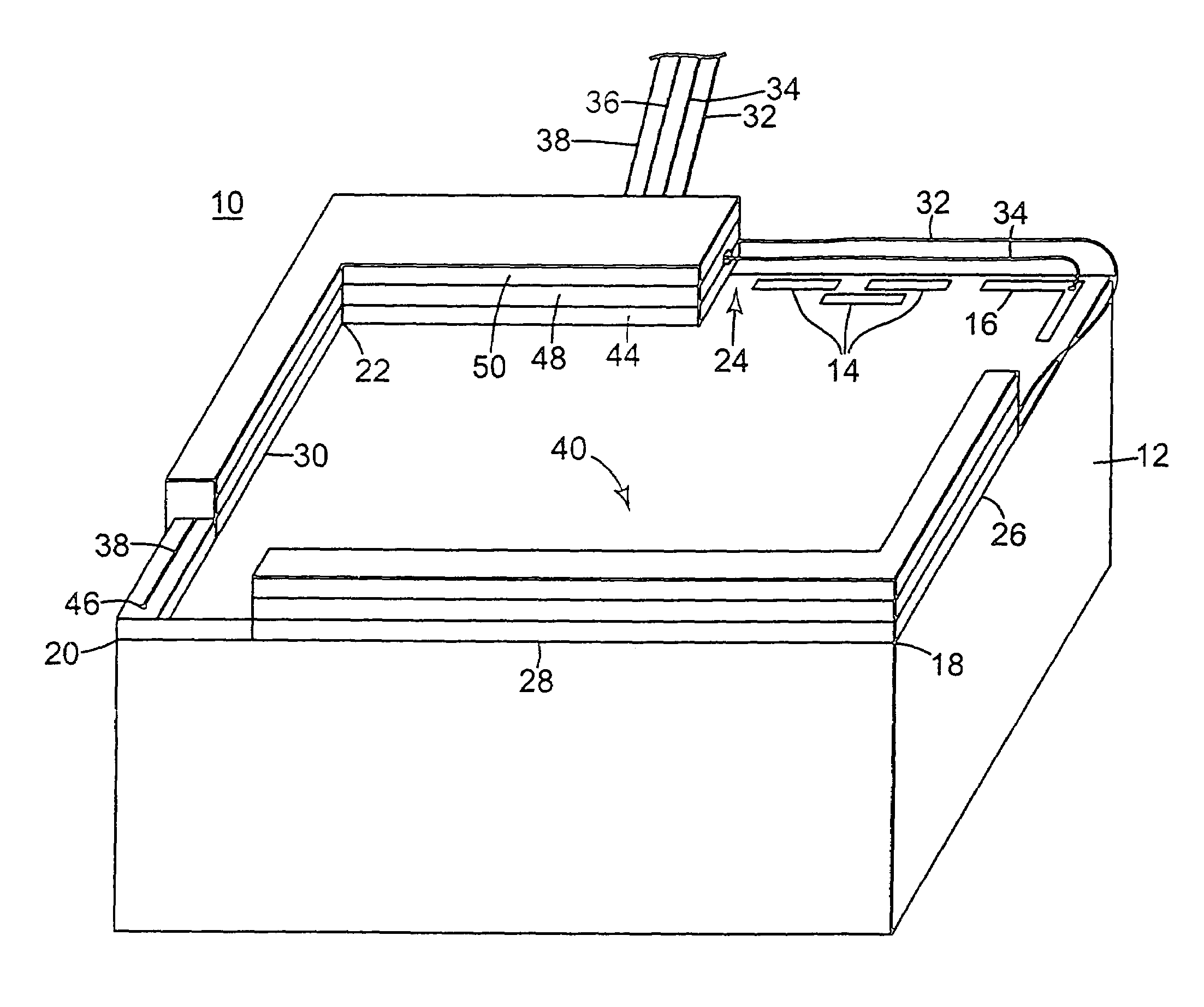
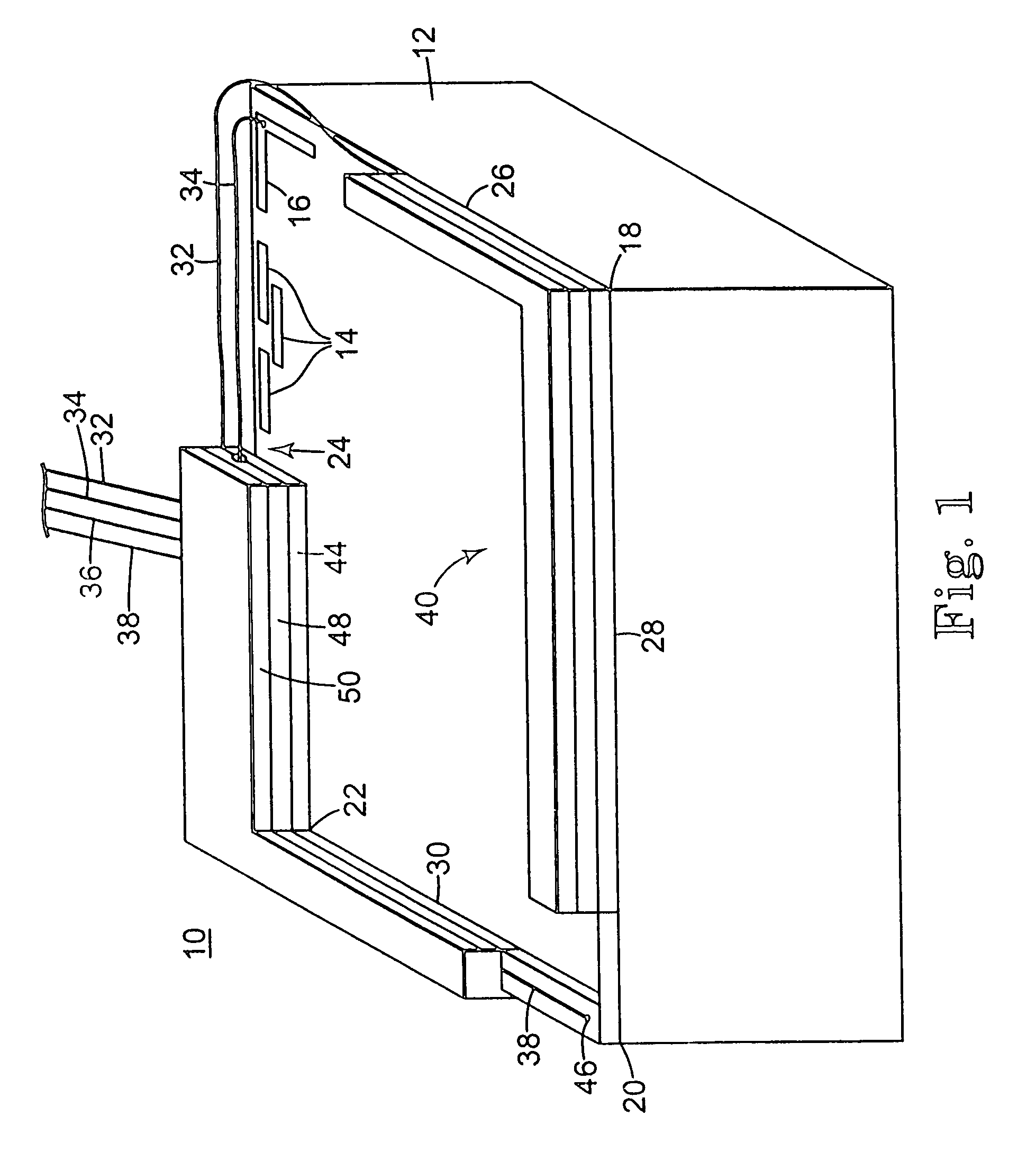
[0051]Prior art touch screen panel 10, FIG. 1, includes substrate 12 which usually includes or is an insulative layer (e.g., glass), a resistive layer over the primary working surface of the insulative layer, and a pattern of edge electrodes 14 and terminal electrodes, usually corner electrodes such as electrode 16, on the resistive layer as is known in the art. There are additional corner electrodes (not shown) one at each other corner 18, 20, and 22 of the touch screen. The edge electrodes 14 repeat in some predetermined patterned fashioned along each edge 24, 26, 28, and 30 of panel 10. In the prior art, wires 32, 34, 36, and 38 extend to each corner electrode and with their ends stripped of insulation are soldered to the respective corner electrodes in order to generate the appropriate electrical field across the working or active surface 40 of panel 10. So, for example, wire 32 extends along edges 24 and 26 of panel 10 to the corner electrode (not shown) at corner 18; wire 34 e...


PUM

PropertyMeasurementUnit
Temperatureaaaaaaaaaa
Pressureaaaaaaaaaa

Abstract

A method of applying an edge electrode pattern to a touch screen. The method includes depositing, on a first surface of a decal strip, conductive material in the form of an edge electrode pattern, placing the first surface of the decal strip on one edge of a touch screen, applying heat and pressure to an opposite surface of the decal strip until the edge electrode pattern is transferred from the first surface of the decal strip to the touch screen; and removing the decal strip.

Description

CROSS REFERENCE TO RELATED APPLICATIONS[0001]This application is a continuation of U.S. application Ser. No. 10 / 050,512, filed Jan. 16, 2002, now abandoned, and is a continuation-in-part of U.S. application Ser. No. 09 / 886,452, filed Jun. 21, 2001, now abandoned, which was a divisional of U.S. application Ser. No. 09 / 365,100, filed Jul. 30, 1999, issued as U.S. Pat. No. 6,280,552.FIELD OF THE INVENTION[0002]This invention relates to a method of applying an edge electrode pattern and also wire traces to a touch screen.BACKGROUND OF THE INVENTION[0003]Touch screen panels generally comprise an insulative (e.g., glass) substrate and a resistive layer disposed on the insulative substrate. A pattern of conductive edge electrodes are then formed on the edges of the resistive layer. The conductive electrodes form orthogonal electric fields in the X and Y directions across the resistive layer. Contact of a finger or stylist on the panel then causes the generation of a signal that is represen...

Claims


Application Information

Patent Timeline
IPC IPC(8): B29C65/02B32B37/02B32B37/14B32B37/20B32B38/14H05K3/20G06F3/045G09F9/00H05K3/28
CPCG06F3/045H05K3/207G06F2203/04113H05K3/20Y10T428/24917H05K2201/0284H05K2201/09436H05K2203/0531H05K3/28
Inventor BOTTARI, FRANK J.MARBLE, ANDREA C.
Owner 3M INNOVATIVE PROPERTIES CO
Learn More