Simultaneous real-time trace and debug for multiple processing core systems on a chip

a technology of multiple processing cores and applied in the field of simultaneous real-time trace data capture, can solve the problems of insufficient above strategies, trace can show problems in the programming of the processing core, point to errors in the processing core hardware, etc., and achieve the effect of facilitating simultaneous real-time trace data

Active Publication Date: 2006-07-18
TENSILICA
View PDF10 Cites 258 Cited by
  • Summary
  • Abstract
  • Description
  • Claims
  • Application Information

AI Technical Summary

Benefits of technology

[0018]The present invention has been made with problems of the prior art in mind and generally facilitates capturing simultaneous real-time trace data from an arbitrary subset of any number of processing cores residing on a single integrated circuit chip (i.e., a system on a chip). Further, the invention selectively collects, stores and analyzes the captured trace data.
[0019]According to one aspect of the invention, coupled to each processing core on the system on a chip (SoC) from which trace data might be desired, is at least one debug output bus. Each debug output bus can be configured to include some or all signals necessary to follow a processing core's operation, and to recreate all or part of the processing core's current state in a software debugger. In addition to the debug output bus, an apparatus according to an example of the invention includes a trace control module. The trace control module receives the real-time trace data from the processing cores and is capable of deciding whether and when to store trace samples into trace memory. The interconnect between the processing cores and the trace control module is another aspect of the invention. According to this aspect, processing core signals are passed via a debug ou

Problems solved by technology

These processing cores can now be quite complex and do substantial amounts of work without predetermined cycle by cycle interaction with other cores on the SoC.
The trace can show problems in the programming of the processing core and point to errors in the processing core hardware.
There are numerous factors in the design of modern multiple processing core SoCs that make the above strategies increasingly insufficient.
First, the speed at which internal logic can operate on a chip is becoming significantly faster than the speed at which IO logic can be routed off and external to the chip.
This is a practical necessity, since handling high-speed signals outside the chip is much more difficult than handling them inside the chip.
Unfortunately, the signals that convey trace data of a processing core off of a chip cannot be slowed down without also slowing down the internal speed of the processing core, since those trace data signals reflect the real-time, internal state of the processing core.
Toggling external IO pins at the internal processing core speed can be either prohibitively expensive or impossible.
A second reason that traditional ICE processing core designs are no longer sufficient is that chip packages are becoming much larger.
In many modern chip designs the chip is said to be pad or IO limited, which means that based on the size of the chip, there is not sufficient room for all the IO signals that the designers would like, or need, to have routed off the chip.
In such environments, adding additional IO signals for the sole purpose of software debugging can seem unnecessarily expensive, if not impossible.
Another problem facing ICE design solutions is that instead of being manufactured on individual chips, processing cores are increasingly being combined together as part of a much larger embedded system, or SoC, on a single

Method used


Image

  • Simultaneous real-time trace and debug for multiple processing core systems on a chip
  • Simultaneous real-time trace and debug for multiple processing core systems on a chip
  • Simultaneous real-time trace and debug for multiple processing core systems on a chip

Examples


Embodiment Construction

[0038]The present invention will now be described in detail with reference to the accompanying drawings, which are provided as illustrative examples of preferred embodiments of the present invention and to enable those skilled in the art to practice the invention. Notably, the figures and examples below are not meant to limit the scope of the present invention. Moreover, where certain elements of the present invention can be partially or fully implemented using known components, only those portions of such known components that are necessary for an understanding of the present invention will be described, and detailed descriptions of other portions of such known components will be omitted so as not to obscure the invention. Further, the present invention encompasses present and future equivalents to the known components referred to herein by way of illustration.

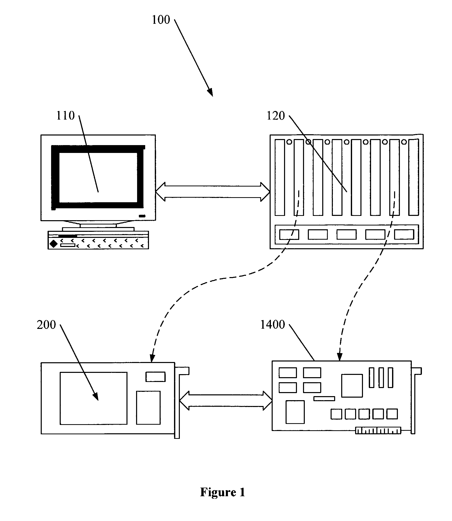
[0039]FIG. 1 shows a presently preferred embodiment of the present invention that encompasses a system 100 for debugging a ...


PUM


Abstract

A system for providing simultaneous, real-time trace and debug of a multiple processing core system on a chip (SoC) is described. Coupled to each processing core is a debug output bus. Each debug output bus passes a processing core's operation to trace capture nodes connected together in daisy-chains. Trace capture node daisy-chains terminate at the trace control module. The trace control module receives and filters processing core trace data and decides whether to store processing core trace data into trace memory. The trace control module also contains a shadow register for capturing the internal state of a traced processing core just prior its tracing. Stored trace data, along with the corresponding shadow register contents, are transferred out of the trace control module and off the SoC into a host agent and system running debugger hardware and software via a JTAG interface.

Description

CROSS-REFERENCE TO RELATED APPLICATIONS[0001]This application is related to U.S. patent application Ser. No. 09 / 680,126 to Newlin et al., the contents of which are hereby incorporated by reference, and which is commonly owned by the present assignee.BACKGROUND OF THE INVENTION[0002]1. Field of the Invention[0003]The present invention is directed to the development of an integrated circuit containing multiple processing cores on a single chip (i.e., a system on a chip). More particularly, the present invention is directed towards tracing and debugging logic and techniques for simultaneously ascertaining and displaying the real-time state of any number of the processing cores on the integrated circuit as they operate.[0004]2. Background of the Related Art[0005]The system on a chip (SoC) field has arisen as the amount of digital logic that can be placed on a single semiconductor chip has substantially exceeded the amount of digital logic required by a single processing core (Throughout...

Claims


Application Information

Patent Timeline
IPC IPC(8): G06F11/00
CPCG06F11/3636
Inventor SONGER, CHRISTOPHER M.NEWLIN, JOHNNUGGEHALLI, SRIKANTHJACOBOWITZ, DAVID GLEN
Owner TENSILICA
Why Eureka
Try Eureka