
Chain motor drive controller

Active Publication Date: 2006-07-25
GEORGE HYRA S MRS +1
View PDF21 Cites 13 Cited by
  • Summary
  • Abstract
  • Description
  • Claims
  • Application Information

AI Technical Summary

Benefits of technology

[0012]The present intervention provides a chain hoist motor control system that is housed entirely within the existing casings of the most popular commercially available chain hoists that are most frequently used in moving theatrical equipment. Consequently, the chain hoist motor control system of the present invention is protected from damage and from being misplaced during transportation and storage. The chain hoist motor control system of the invention is protected by the sturdy casing of the chain hoist and cannot become separated from the chain hoist or misplaced.
[0013]Furthermore, the position sensing apparatus for the chain hoist motor controller of the invention is considerably more accurate than conventional systems because the positional information is derived from the chain hoist motor shaft itself through a direct, mechanical connection between the rotary drive shaft of the chain drive motor and the position sensor of the position encoder.
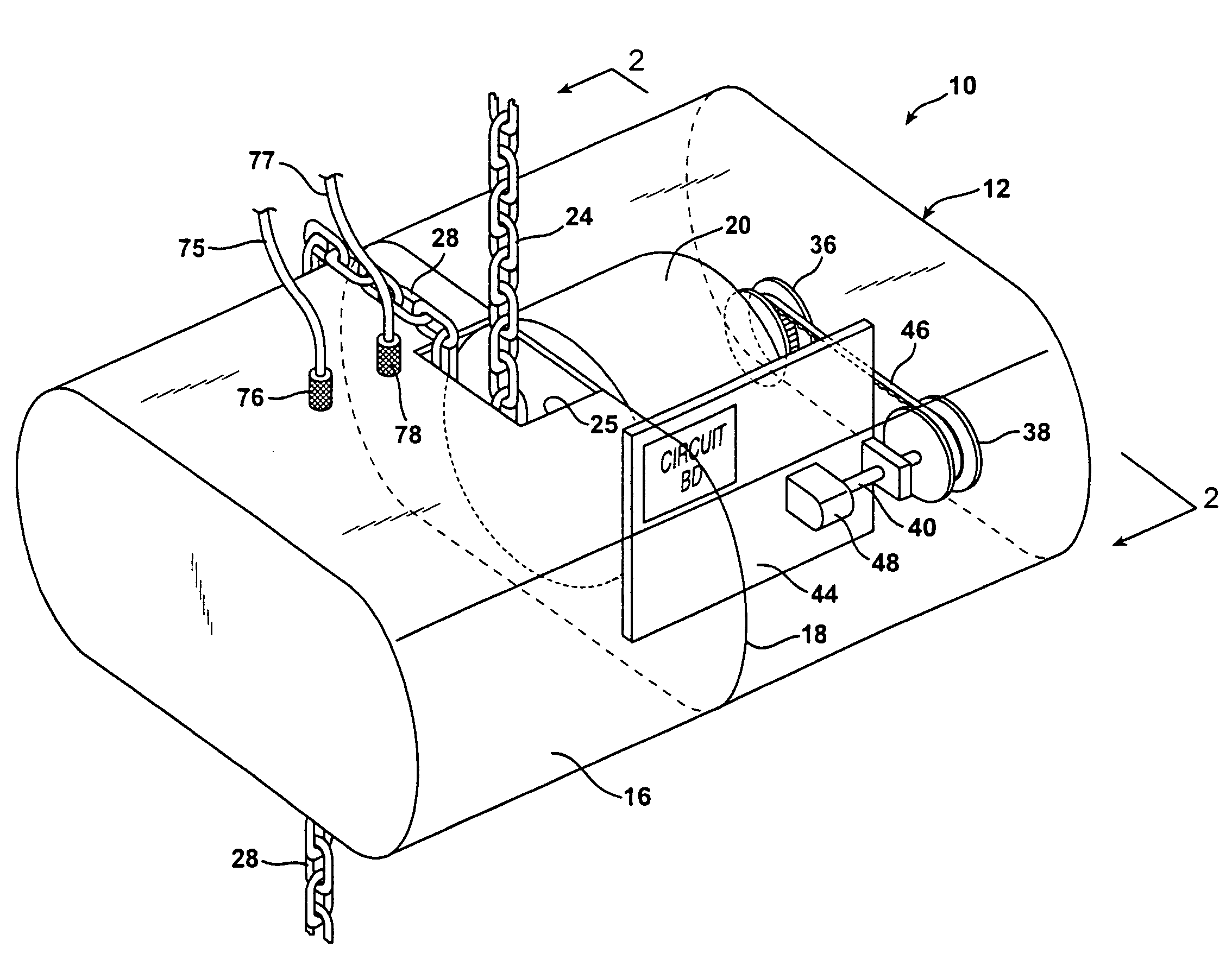
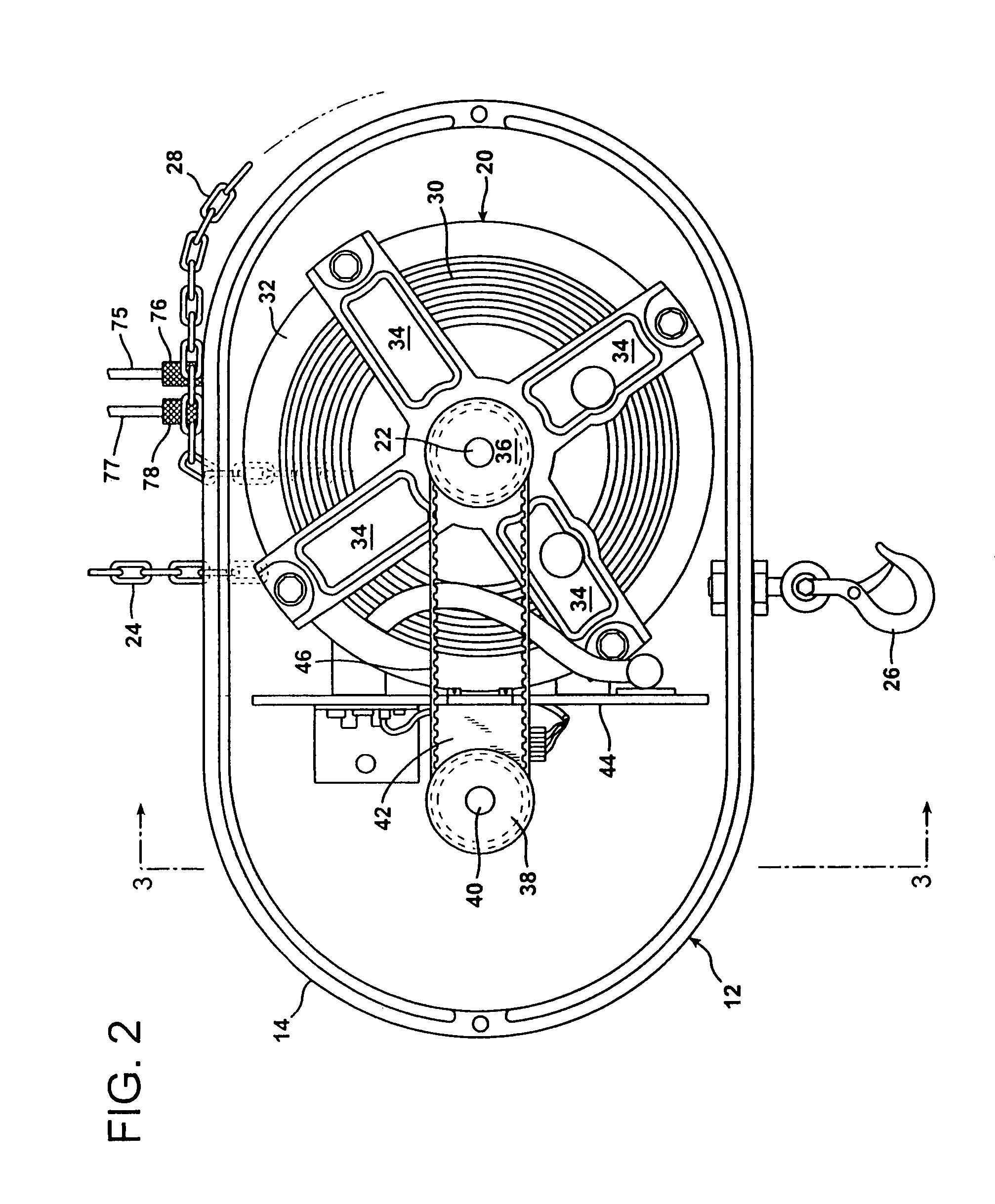
[0016]A pulley and drive belt coupling system is particularly advantageous since in conventional, commercially available chain drives there is a retaining nut at the end of the chain hoist motor rotary drive shaft opposite the chain-engaging mechanism. The kind of motor pulley utilized according to the invention is internally threaded and is engaged on the end of the motor drive shaft in place of the retaining nut. The motor pulley thereby serves the dual function of a retaining nut and also part of the mechanism that transmits rotary motion from the rotary drive shaft directly to the position sensor of the position encoder. By physically or mechanically coupling the movement of the chain drive motor rotary drive shaft directly to the position sensor the system of the invention achieves greater sensitivity to movement and exerts much tighter control over the movement and location of the chain hoist.
[0017]The entire mechanical coupling mechanism that transmits rotary motion from the rotary drive shaft to the position sensor is located entirely within the existing casing of the chain hoist. This feature is particularly advantageous since chain hoists of the type utilized in the motion picture industry to move theatrical lighting and other equipment are frequently moved from one location to another. For protection and convenience of handling chain hoists are packed within form fitting shipping cases that have interior, padded surfaces configured to snugly seat the chain hoist casings within the shipping cases. There is no room in the shipping cases for any auxiliary equipment, such as separate housings for a mechanical coupling or a chain motor drive controller. Consequently, such ancillary equipment is typically packed and moved in different containers. However, since such auxiliary equipment is packed and moved separately, there is always the problem of locating it and reattaching it to the chain hoist once the chain hoist arrives and is to be deployed at a new location. The present invention solves this problem by locating both the mechanical coupling that transmits rotary motion from the rotary drive shaft directly to the position sensor and also the chain motor drive controller physically within the chain hoist casing. This arrangement not only protects the mechanical coupling mechanism and chain motor drive controller from becoming lost or separated from the chain hoist, but also physically protects it from damage since it is housed within the sturdy chain hoist casing.
[0018]The chain motor drive controller of the present invention has other very significant advantages as well. The chain motor drive controller of the present invention operates at a variable speed in such a manner as to accelerate rotation of the chain drive motor rotary drive shaft when commencing movement from a stopped position and to decelerate rotation of the chain drive motor rotary drive shaft when the difference between the chain hoist location as determined by the position sensor and the desired destination approaches zero. That is, the driving signals to the chain hoist motor ramp up when the chain hoist is first moved and ramp down as it approaches its destination. Furthermore, the variable speed control of the invention allows the chain motor to creep slowly to a desired destination. This allows a suspended load to be held and moved much more steadily than is possible with conventional chain motor drive controller systems. The present invention avoids shaking or bouncing of the load that is characteristic of conventional chain hoist controllers, particularly at the commencement and at the cessation of repositioning.

Problems solved by technology

Where precision control of a chain hoist is necessary, visual observation and corresponding adjustment utilizing manual controls is very inadequate and unacceptable.
However, all of these conventional systems have certain drawbacks.
However, errors are introduced into this system due to stretching of the cable or twisting of the chain, depending upon the load and its orientation.
Furthermore, because the system operates at a single speed, there is a jarring or bounce that occurs when the load arrives at its destination and the motor is shut off.
This system employs magnetic or optical sensors located on a cable take-up reel and entails the same problems of discrepancies between the position as sensed by rotation of the take-up reel and the actual position which is determined by rotation of the chain hoist motor shaft.
Consequently, the load is subjected to a jarring or bouncing effect both when it is initially moved from a stationary position and also when it arrives at its destination.
Furthermore, the prior systems for operating chain hoists require a considerable amount of hardware and electrical components that must be packed separately and transported separately from the chain hoist itself.

Method used


Image

  • Chain motor drive controller
  • Chain motor drive controller
  • Chain motor drive controller

Examples


Embodiment Construction

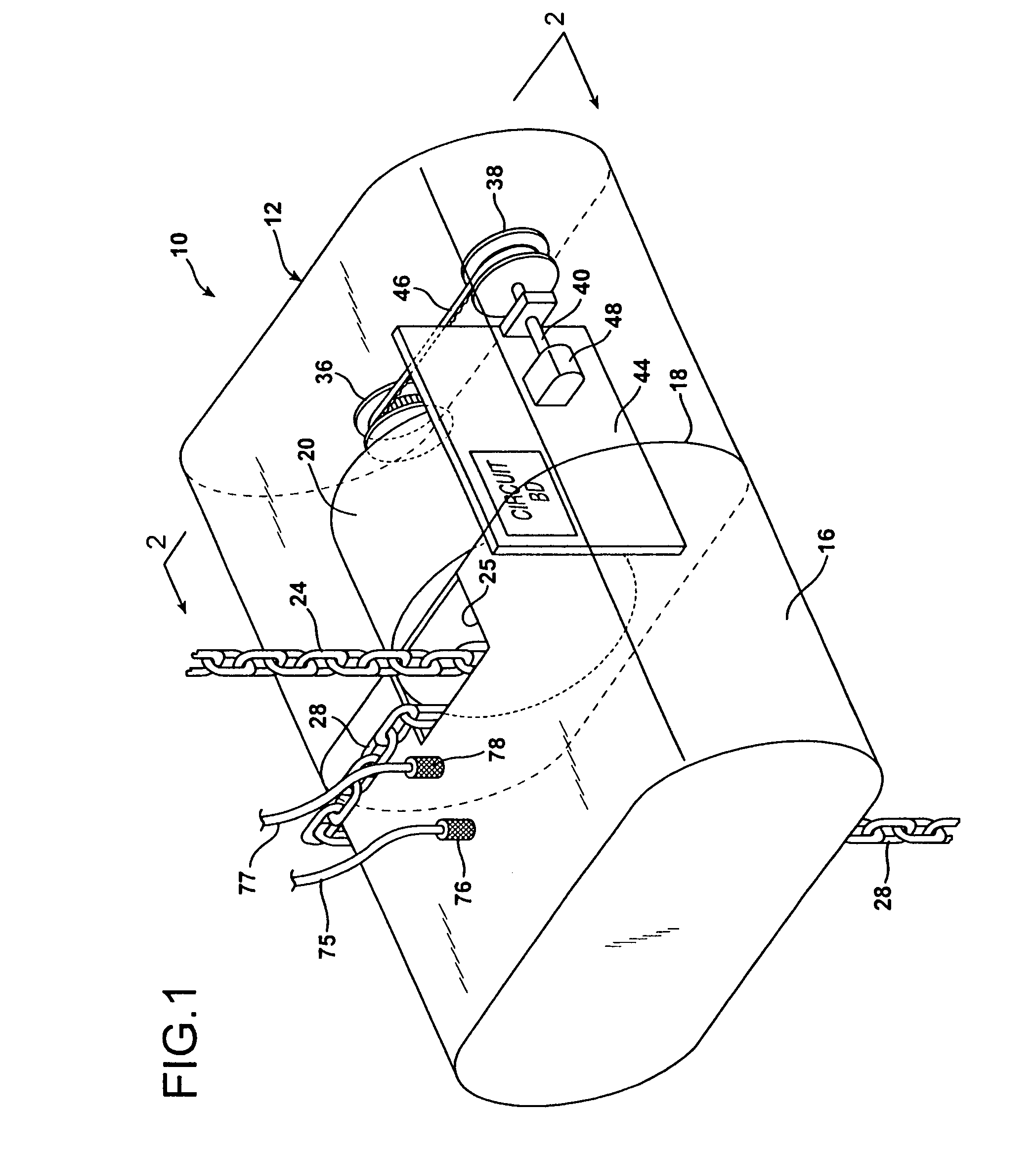
[0031]FIG. 1 illustrates a conventional general purpose chain hoist 10 of the type widely utilized in the theatrical industry for moving lights, scenery, and other heavy loads. For example, the chain hoist 10 may be a CM Lodestar one ton Model LL chain hoist sold by Columbus McKinnon Corp., located at 140 John James Audubon Parkway, Amherst, N.Y. 14228-1197. However, it is to be understood that the invention is not limited to use with this particular chain hoist alone, and may be utilized with many different commercially available chain hoists.

[0032]The chain hoist 10 has operating components housed within a casing 12 formed of a mating pair of rugged, durable casing shell portions 14 and 16 that fit together and meet at an interface demarcation 18. The casing shell portions 14 and 16 are secured to each other in a conventional manner by screws and bolts (not shown). Together, the shell sections 14 and 16 form an encapsulated casing that houses a heavy-duty, bidirectional, variable ...


PUM


Abstract

An improved chain motor drive controller is provided for a chain hoist. The system employs a position encoder including a position sensor located within the casing of the chain hoist to producing encoded electrical position signals. A motor pulley is mounted on the chain motor rotary drive shaft and is coupled by a cogged belt to rotate an encoder pulley that is mounted on the same shaft as the position sensor. A mechanical coupling is thereby provided entirely within the casing of the chain hoist to transmit rotary motion from the rotary drive shaft directly to the position sensor. Also, tracking circuitry, likewise located entirely within the chain hoist casing, receives electrically encoded destination signals and compares these to signals from the position sensor. The tracking circuitry accelerates rotation of the chain motor drive shaft starting from a stationary condition and decelerates rotation of the chain motor drive shaft as the differences between the encoded position signals and the encoded destination signals approach zero.

Description

BACKGROUND OF THE INVENTION[0001]1. Field of the Invention[0002]The present invention relates to a chain hoist motor drive controller which is housed entirely within the casing of a chain hoist to track and control the movement of the load carried by the chain hoist relative to a fixed location.[0003]2. Description of the Prior Art[0004]Chain hoists are utilized in many different applications to raise and lower loads suspending from overhead supports. A chain hoist is comprised of a heavy-duty motor housed within a rugged casing and having at least one chain access opening in the casing. A chain may be suspended from an overhead support or from the chain hoist itself to carry a load. In either case the chain is routed around a chain drive gear located within the chain hoist casing. The chain drive gear within the casing is driven by the chain hoist motor. The slack portion of the chain, after passing around the drive gear within the casing, is routed back out through the chain openi...

Claims


Application Information

Patent Timeline
IPC IPC(8): B66D1/50B66D1/12
CPCB66D3/18
Inventor GEORGE, DAVID WBRACEGIRDLE, GLENN R.PEPPARD, JOSEPHBOOTH, THOMAS G.GUTH, CHRISTOPHER E.
Owner GEORGE HYRA S MRS
Learn More