Eureka AIR delivers breakthrough ideas for toughest innovation challenges, trusted by R&D personnel around the world.

LED warning signal light and row of LED's

a warning signal and led technology, applied in the direction of fixed installation, lighting and heating equipment, lighting support devices, etc., can solve the problems of increasing the size of the light bar, adversely affecting the aerodynamic characteristics of the vehicle, and relying on mechanical components to revolve, etc., to achieve the effect of prolonging the life cycl

Inactive Publication Date: 2006-07-25
SAFARILAND
View PDF274 Cites 18 Cited by
  • Summary
  • Abstract
  • Description
  • Claims
  • Application Information

AI Technical Summary

Benefits of technology

[0042]A principal advantage of the present invention is to provide a warning signal light capable of simulating revolving or oscillating light signals without the use of mechanical components.
[0043]Another principal advantage of the present invention is that the warning signal light is capable of producing several different types of light signals or combinations of light signals.
[0044]Still another principal advantage of the present invention is to be rugged and have a relatively longer life cycle than traditional warning signal lights.
[0045]Still another principal advantage of the present invention is to produce a truer or pure light output color without the use of filters.
[0046]Still another principal advantage of the present invention is to allow the user to adjust the color of the light signal without having to make a physical adjustment from a multi-colored panel.
[0047]Still another principal advantage of the present invention is that it may be formed into various shapes. This allows the invention to be customized for the particular need.

Problems solved by technology

Many problems exist with the known methods for producing warning light signals.
One particular problem with known light sources is their reliance on mechanical components to revolve or oscillate the lamps to produce the desired light signal.
Additionally, these components increase the size of the light bar or emergency lights which may adversely affect the vehicles aerodynamic characteristics.
Moreover, there is an increased likelihood that a breakdown of the light bar or light source will occur requiring the repair or replacement of the defective component.
Finally, the known light bars and sources require a relatively large amount of electrical current during operation.
The demands upon the electrical power system for a vehicle may therefore exceed available electrical resources reducing optimization of performance.
These lamps emanate large amounts of heat which is difficult to dissipate from a sealed light enclosure or emergency light and which may damage the electronic circuitry contained therein.
In addition, these lamps consume large amounts of current requiring a large power supply or large battery or electrical source which may be especially problematic for use with a vehicle.
These lamps also generate substantial electromagnetic emissions which may interfere with radio communications for a vehicle.
Finally, these lamps, which are not rugged, have relatively short life cycles necessitating frequent replacement.
Another problem with the known warning signal lights is the use of filters to produce a desired color.
Furthermore, filters fade or flake over time rendering the filters unable to consistently produce a desired color for observation in an emergency situation.
These problems associated with traditional signaling lamps are exacerbated by the fact that creating multiple light signals requires multiple signaling lamps.
Further, there is little flexibility in modifying the light signal created by a lamp.
For example, changing a stationary lamp into one that rotates or oscillates would require a substantial modification to the light bar which may not be physically or economically possible.
A problem with the prior art is the cost and failure rate of the known “unmarked corner tubes,” or “dome lights.” The failure rate of these devices frequently results in a significant amount of “down time” for a vehicle to effectuate replacement.
Further, an officer is frequently unaware that a vehicle light is inoperative requiring replacement.
This condition reduces the safety to an officer during the performance of his or her duties.
In addition, the reduced life cycle and failure rate of the known illumination devices significantly increases operational costs associated with material replacement and labor.
The color blue is particularly hard to produce in this manner.
Corrosive effects may destroy the trigger wire and the wire contacts leading to the anode and cathode.
Corrosion is enhanced because of the high heat generating characteristics of the lamp which may heat the air inside the lamp fixture when the lamp is in use, and this heated air may condense when the lamp is off resulting in moisture buildup inside the fixture.
The buildup of moisture may result in the shorting out of the electrical wires and degrade the performance of the emission wire, sometimes preventing proper ionization of the gas within the xenon gas discharge lamp.
Warning lights, due to the type of light source utilized, may be relatively large in size which in turn may have an adverse affect upon adjacent operational components.
In addition, there is an increased likelihood for a breakdown of the light source requiring repair or replacement of components.
Another problem with the known warning signal lights is the use of rotational and / or oscillating mechanisms which are utilized to impart a rotational or oscillating movement to a light source for observation during emergency situations.
These mechanical devices are frequently cumbersome and difficult to incorporate and couple onto various locations about a vehicle due to the size of the device.
These mechanical devices also frequently require a relatively large power supply to engage and operate the device to impart rotational and / or oscillating movement for a light source.
Another problem with the known warning signal lights is the absence of flexibility for the provision of variable intensity for the light sources to increase the number of available distinct and independent visual light effects.
Also, no warning light signals are known which provide a regular pattern of variable or modulated light intensity for a warning signal light to provide a desired type of lighting effect.
Further, no warning light signals are known which combine a desired type of light effect with either irregular variable light intensity or regular modulated light intensity to provide a unique and desired combination lighting effect.
It has also not been known to provide alternative colored LED light sources which may be electrically controlled for the provision of any desired pattern of light signal such as flashing, pulsating, oscillating, modulating, rotational, alternating, strobe, and / or combination light effects.
Other problems associated with the known warning signal lights relate to the restricted positioning on a vehicle due to the size and shape of the light source.
Light bars or light sources generally extended perpendicular to the longitudinal axis of a vehicle and were therefore more difficult to observe from the sides by an individual.
Observation from the sides, or at an acute angle relative to the sides, frequently resulted in reduced observation of emergency lights during an emergency situation.

Method used


Image

  • LED warning signal light and row of LED's
  • LED warning signal light and row of LED's
  • LED warning signal light and row of LED's

Examples


Embodiment Construction

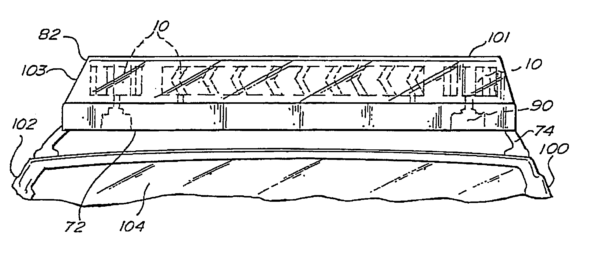
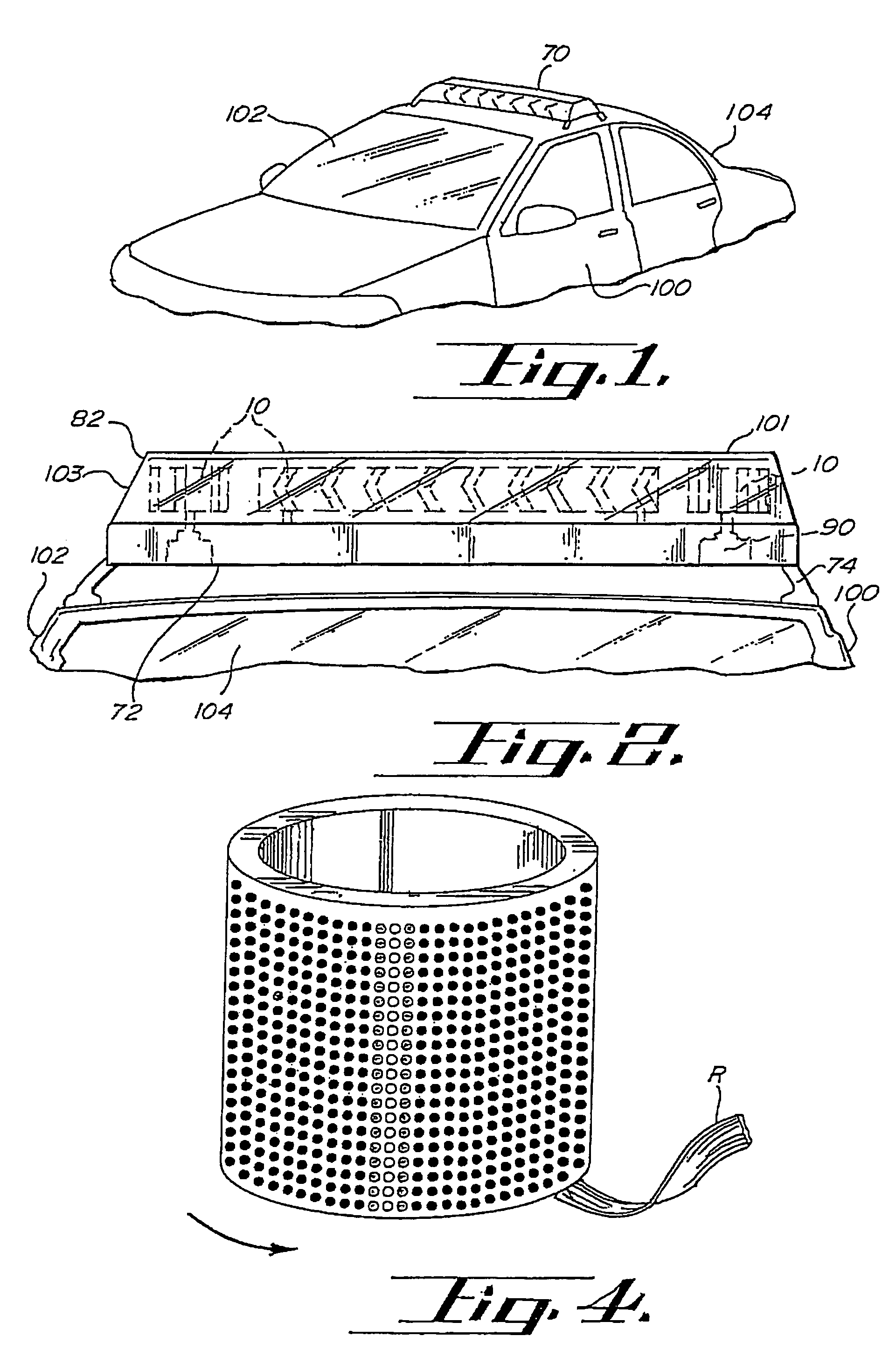
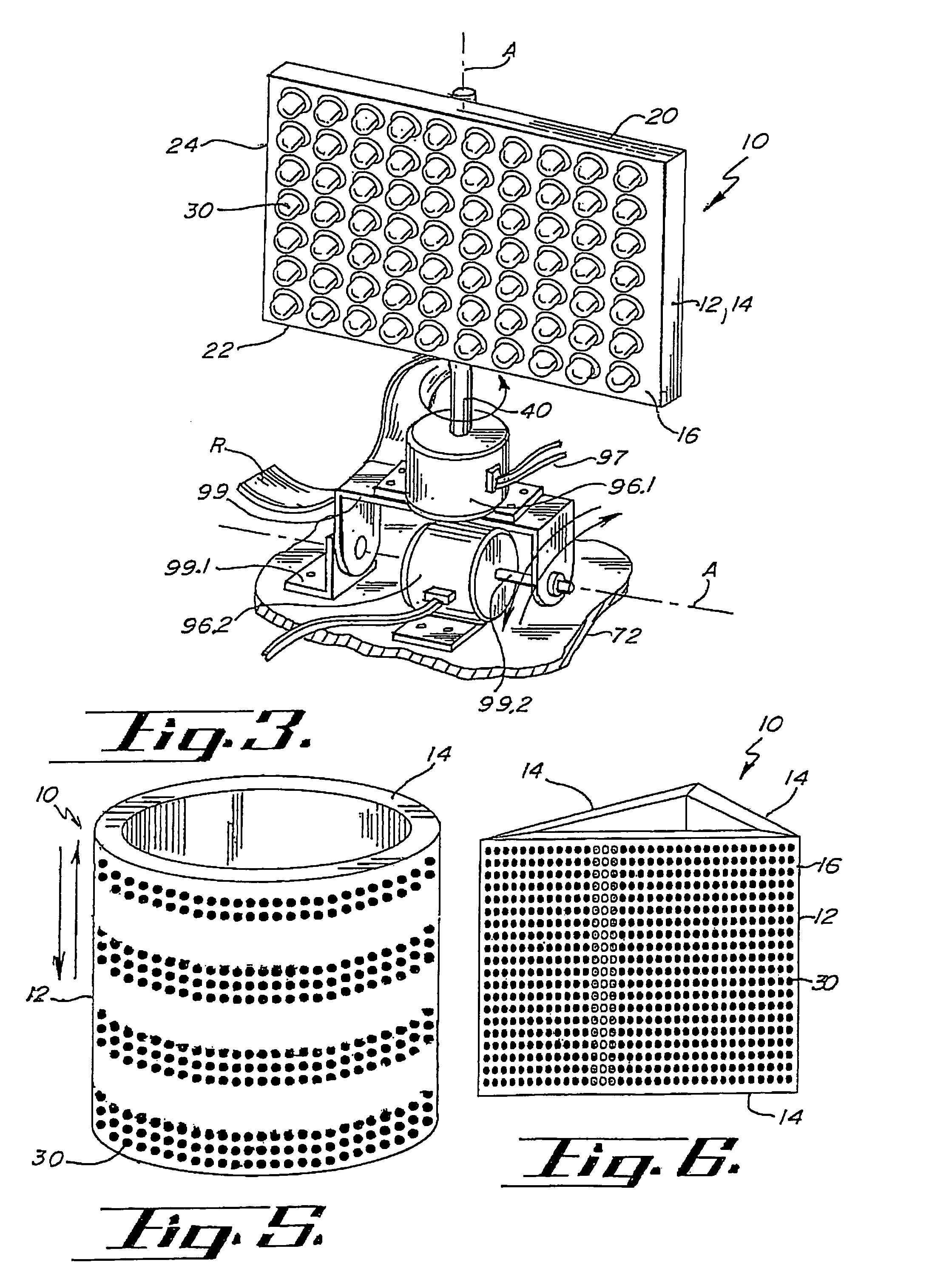
[0159]A warning signal light according to the principles of the invention is indicated generally herein as numeral 10. FIGS. 1 and 2 depict light bar 70 mounted to an emergency vehicle 104. Light bar 70 includes base 72, mounting means 74, cover 82, and warning signal lights 10. Also included in light bar 70 are gyrators 90 used to impart motion to warning signal lights 10.

[0160]Referring to FIGS. 3 and 9, warning signal light 10 comprises light support 12, light sources 30, controller 50 (shown in FIG. 11), and connecting portion 40 for attaching the warning signal light 10 to light bar 70 or gyrator 90. The warning signal light 10 operates to create a warning signal for use by an emergency vehicle 104 by selectively activating light sources 30 using controller 50. Alternatively, warning signal light 10 may be formed of a solitary LED light source 30 at the discretion of an individual.

[0161]Light sources 30 are preferably light emitting diodes (LED's) and are generally arranged in ...


PUM


Abstract

A light emitting diode (LED) warning signal light, the warning signal light comprising a plurality of light sources constructed and arranged with a reflector or cullminator, the LED light source being in electrical communication with a controller and a power supply, battery, or other electrical source. The warning signal light provides various colored light signals for independent use or use by an emergency vehicle. These light signals may include a strobe light, revolving light, an alternating light, a flashing light, a modulated light, a pulsating light, an oscillating light or any combination thereof. Additionally, the warning signal light may be capable of displaying symbols, reverse characters, or arrows. The controller may further be adapted to regulate or modulate the power intensity exposed to the illuminated LED's to create a variable intensity light signal.

Description

CROSS-REFERENCE TO RELATED APPLICATIONS[0001]This application is a Divisional application from Ser. No. 10 / 016,989, filed Dec. 13, 2001 now U.S. Pat. No. 6,789,930, which is a divisional of U.S. patent application Ser. No. 09 / 586,221, filed Jun. 2, 2000, which issued Mar. 16, 2004, as U.S. Pat. No. 6,705,745 B1, which claims priority to Provisional Patent Application Ser. No. 60 / 138,408, filed Jun. 8, 1999, the entire contents of all of which are hereby incorporated herein by reference in their entireties.[0002]The present invention relates to a light emitting diode (LED) warning signal light having modulated power intensity for use by emergency vehicles and is based upon Provisional U.S. Patent Application No. 60 / 138,408, filed Jun. 8, 1999, which is incorporated herein by reference in its entirety.BACKGROUND OF THE INVENTION[0003]Light bars or emergency lights of the type used on emergency vehicles such as fire trucks, police cars, and ambulances, utilize warning signal lights to ...

Claims


Application Information

Patent Timeline
Patent Type & Authority Patents(United States)
IPC IPC(8): G08B5/22F21V21/30B60Q1/26B60Q1/52F21K99/00F21S10/06
CPCB60Q1/2611B60Q1/2696B60Q1/52F21K9/00F21K9/30F21S10/06F21Y2111/007F21Y2101/02Y10S362/80F21V17/12F21Y2111/005F21W2101/02F21K9/20F21Y2107/30F21Y2107/40F21Y2115/10F21S43/14F21S43/195F21S43/30F21S45/47F21W2107/10
Inventor PEDERSON, JOHN C.
Owner SAFARILAND
Why Eureka
Eureka Blog
Learn More