Device and method for determining a malfunction in a filter

Inactive Publication Date: 2006-07-25
ROBERT BOSCH GMBH
View PDF14 Cites 11 Cited by
  • Summary
  • Abstract
  • Description
  • Claims
  • Application Information

AI Technical Summary

Benefits of technology

[0012]According to the exemplary method according to the present invention, the frequency response characteristic and the frequency distribution of the signals of the two gas sensors are recorded over a period of time and related to each other. In this manner, the occurrence of failures of the filter to be monitored can be detected in an easy and prompt manner.
[0013]A failure of the filter to be monit

Problems solved by technology

Until now, no methods, in particular, no methods suitable for mass application in automotive applications are known to allow measurement of leaks or cracks in such a soot filter dur

Method used


Image

  • Device and method for determining a malfunction in a filter
  • Device and method for determining a malfunction in a filter
  • Device and method for determining a malfunction in a filter

Examples


Embodiment Construction

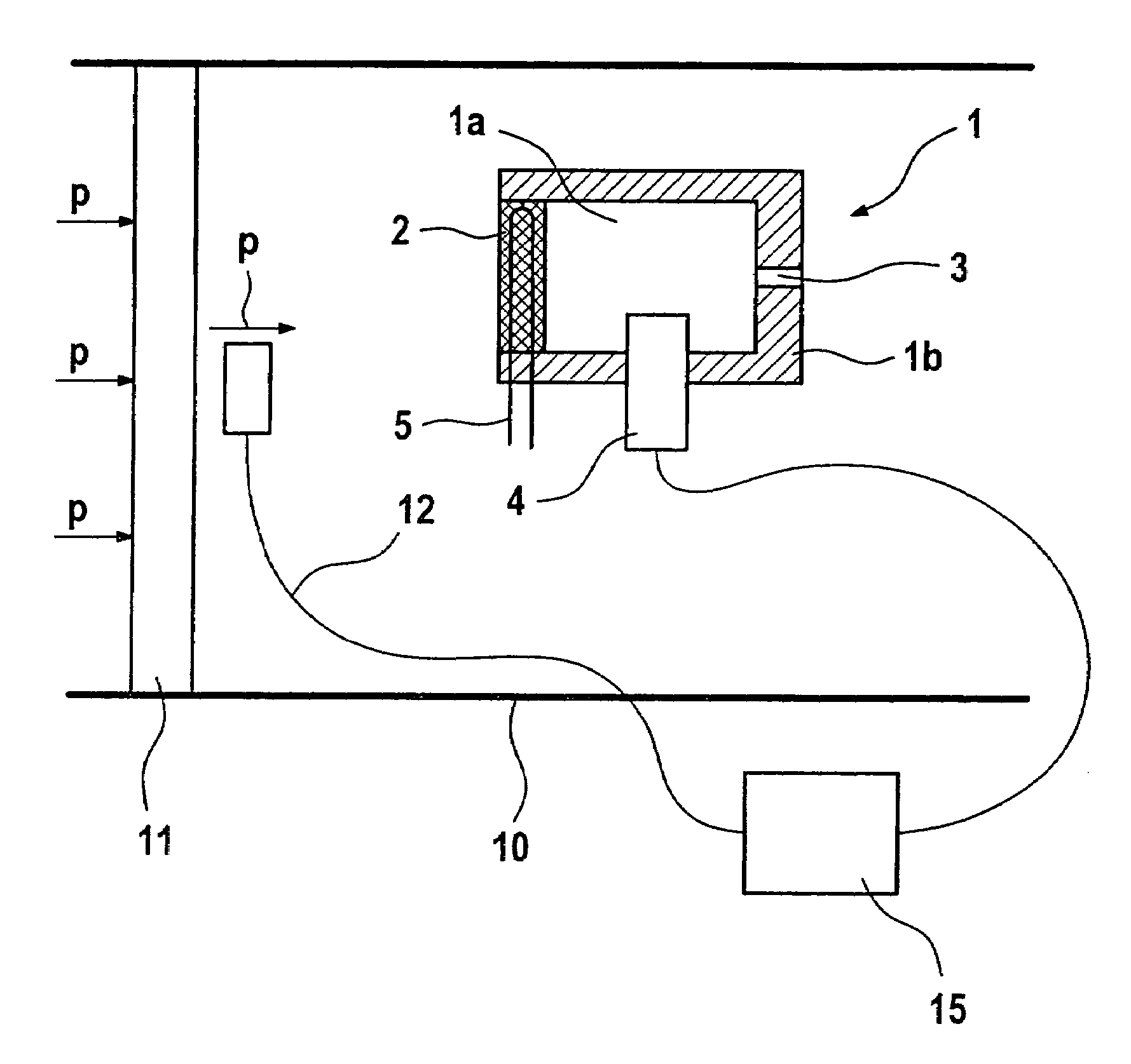
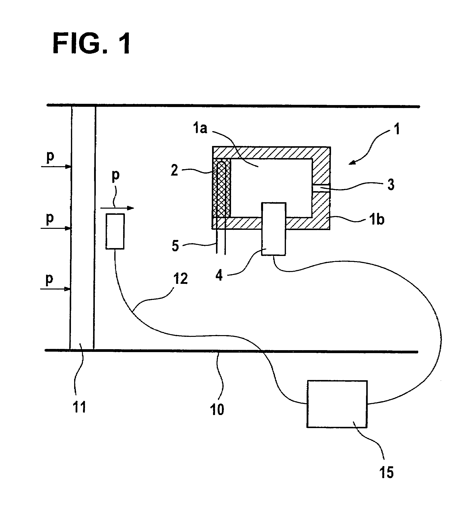
[0016]In FIG. 1, a chamber provided within the scope of the device according to an exemplary embodiment of the present invention is denoted by 1 in its entirety. Chamber 1 is bounded on one side by a filter body 2 and for the rest by a wall 1b. The interior space (dead volume) of the chamber defined in this manner is denoted by 1a. The chamber configured in this manner is mounted in an exhaust branch 10 of a Diesel engine downstream of a soot filter 11 to be monitored. It should be emphasized at this point that all components shown are represented in a purely schematic way. The flow direction of the exhaust gas in the exhaust branch is illustrated by arrows P.

[0017]It can be seen that the flow of exhaust gas approaches filter body 2 from the front. On its rear side, chamber 1 has an outflow opening 3 through which exhaust gas or gas that has entered space 1a through filter body 2 can exit this space.

[0018]Moreover, chamber 1 shown is designed to include an exhaust gas sensor 4, whic...


PUM

PropertyMeasurementUnit
Timeaaaaaaaaaa
Flow rateaaaaaaaaaa
Concentrationaaaaaaaaaa

Abstract

A device for detecting a failure of a filter used to clean a gas stream, in particular an exhaust gas stream, of soot particulates, including a chamber which is insertable into the gas stream to be cleaned in addition to the filter and which is at least partially closed by a filter body and has at least one opening through which gas entering the chamber through the filter body can exit the chamber, at least one gas sensor for determining the concentration of at least one component of the gas to be cleaned being arranged in the chamber, and at least one second gas sensor for determining the concentration of the at least one component of the gas to be cleaned being arranged outside the chamber.

Description

FIELD OF THE INVENTION[0001]The present invention relates to a device and a method for detecting a failure of a filter.BACKGROUND INFORMATION[0002]In particular in the case of Diesel combustion engines, it is of importance that the level of soot particulates emitted into the environment be kept as low as possible. To this end, it is useful to monitor the soot particulate emission while the combustion engine is in operation using a sensor mounted in the exhaust branch. In this context, the sensor can be placed downstream or upstream of a soot filter mounted in the exhaust branch. If the sensor is placed in the exhaust branch downstream of the soot filter, the sensor can also be used for monitoring the performance of the soot filter.[0003]Moreover, the concentration of soot particulates in an exhaust gas of a combustion engine may be measured continuously, that is during the normal operation of the engine, to allow direct detection of changes in the engine behavior, for example, becau...

Claims


Application Information

Patent Timeline
IPC IPC(8): B01D46/00B01D46/42F02D45/00F01N3/02F01N3/027F01N11/00
CPCF01N3/027F01N11/00F01N11/007Y10S55/10F01N2560/05Y02T10/47Y10S55/30F01N2550/04Y02T10/40
Inventor SCHULTE, THOMASSCHUMANN, BERND
Owner ROBERT BOSCH GMBH
Why Eureka
Try Eureka