
Pulsed UV light source

a light source and ultraviolet light technology, applied in the field of pulsed ultraviolet light sources, can solve the problems of high throughput industrial purposes, difficult to effectively transfer the energy to the substance or entity to be treated, and difficult to efficiently provide sufficient excitation energy to the pulsed source, so as to prevent dna recovery and eliminate biological contaminants and pests.

Inactive Publication Date: 2006-07-25
SEVEN TRENT WATER PURIFICATION INC
View PDF45 Cites 38 Cited by
  • Summary
  • Abstract
  • Description
  • Claims
  • Application Information

AI Technical Summary

Benefits of technology

[0024]The waveguide controls the flow of ultraviolet radiation therefrom. The control function typically includes the prevention of the release of harmful or unnecessary ultraviolet radiation frequencies.
[0032]Suitably, the waveguide or any sleeve therefor is coated with a coating which assists in controlling the flow of ultraviolet and / or microwave energy therefrom. The coating may be applied to either or both of the inner or outer surfaces of the waveguide. Partial coatings are also envisaged.
[0035]In aspects, any sleeve for the waveguide and / or the ultraviolet bulb is coated with a coating that assists in modifying the wavelength of emitted light.
[0053]The sterilising method aspect herein is suitable for use in sterilising a variety of substances including water for human consumption; waste water and sewage; metallic and non-metallic objects including medical instruments; air in buildings such as hospitals, offices and homes; and in prolonging the shelf-life of foodstuffs (e.g. fruit and vegetables) by killing bacteria on the surface thereof.
[0067]In another method aspect herein, the exposure of a biological substance to wavelengths of less than 200 nm or from 300–400 nm has been found to help to prevent DNA recovery. This may for example, be of use in the elimination of biological contaminants and pests e.g. insects.

Problems solved by technology

One problem such systems is that it is difficult to efficiently provide sufficient excitation energy to the UV source and difficult to effectively transfer that energy to the substance or entity to be treated.
It is therefore difficult to arrange systems for high energy, high throughput industrial purposes.

Method used


Image

  • Pulsed UV light source
  • Pulsed UV light source
  • Pulsed UV light source

Examples


Embodiment Construction

[0083]The present invention is here described by means of examples, which constitute possible embodiments of the invention.

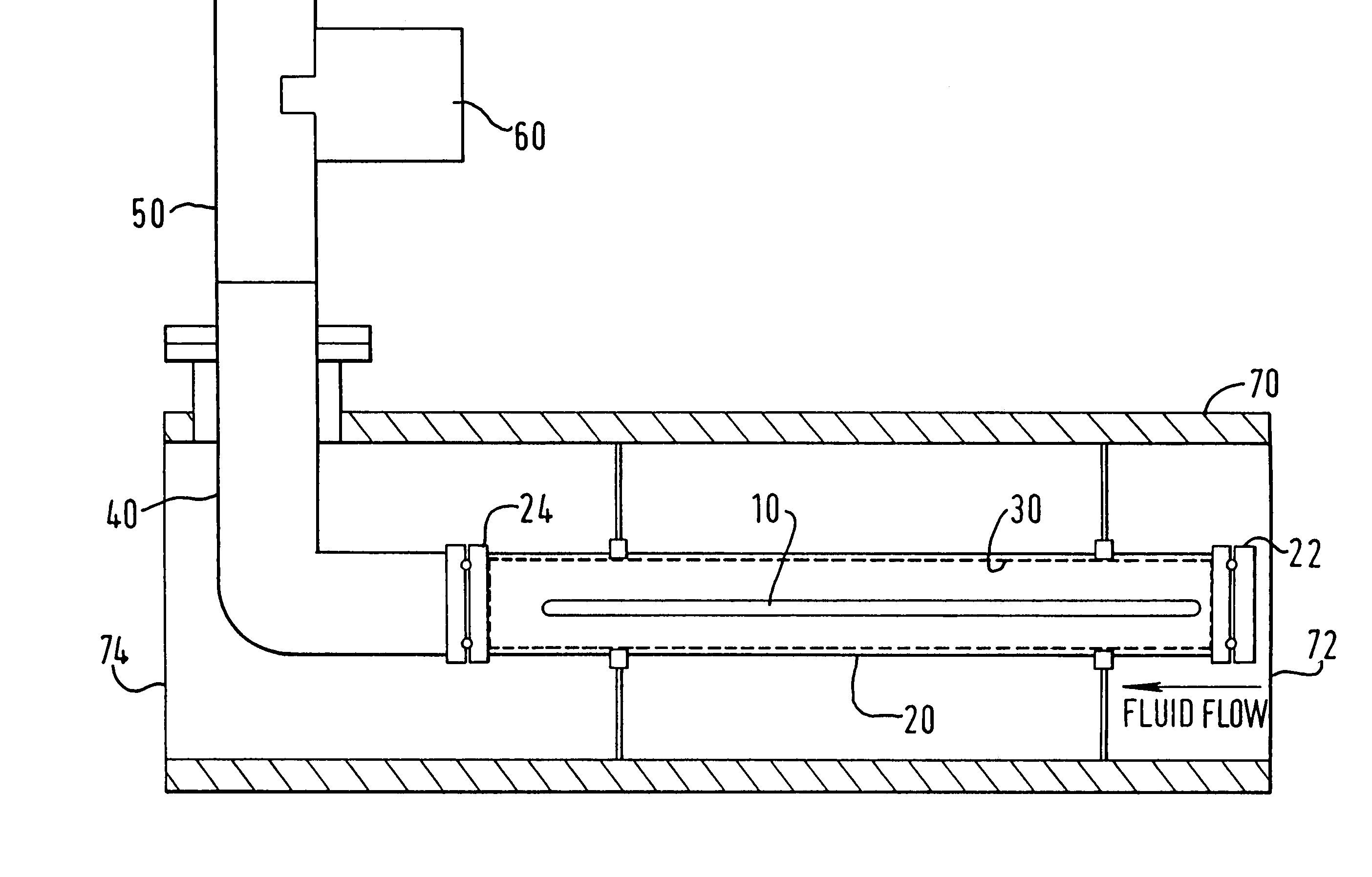
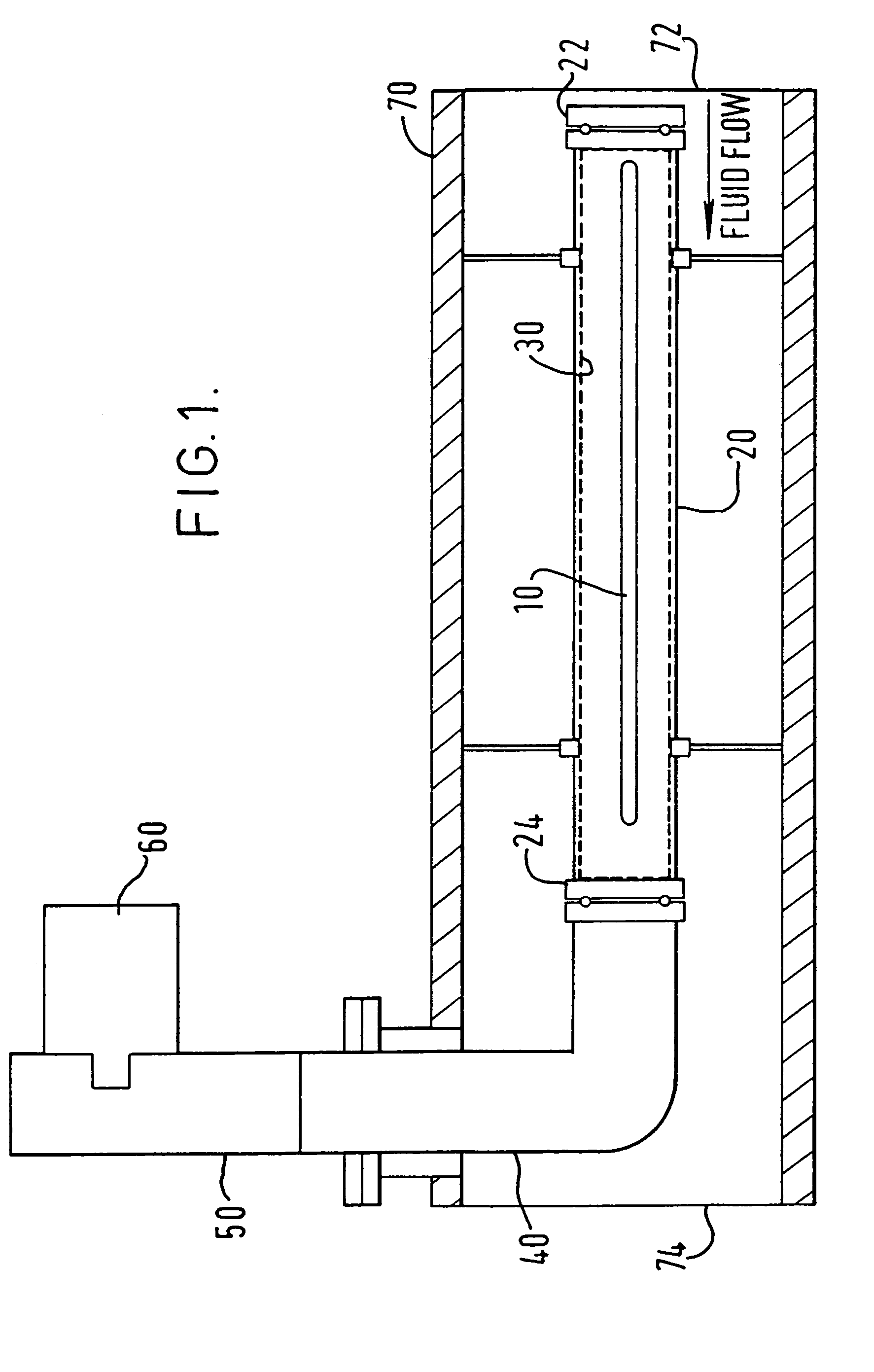
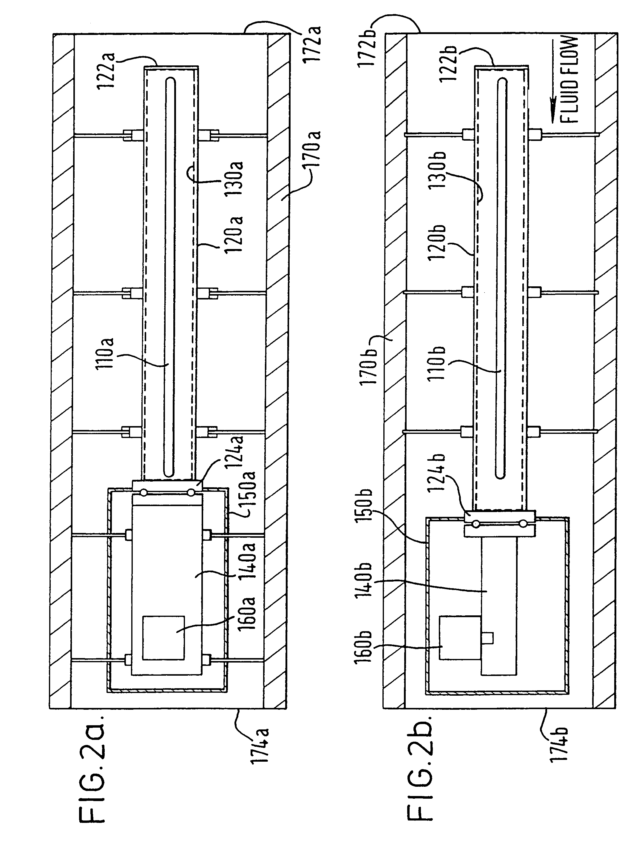
[0084]FIG. 1 shows an ultraviolet light source comprising an ultraviolet lamp 10 enclosed by cylindrical enclosure 20. The cylindrical walls of the enclosure 20 are comprised of quartz material which is transparent to UV radiation. A conducting copper mesh 30 is provided to act as a waveguide. First end of the cylindrical enclosure has blocking end flange 22 provided thereto. The second end is provided with coupling flange 24 which couples with right angled pathguide 40 which in turn connects with rectangular pathguide 50. Magnetron 60 acts as a pulsed microwave energy source to feed pulsed microwave energy into the rectangular waveguide 50, thence into the right angled pathguide 40 and finally to the ultraviolet lamp 10 which is excited thereby.

[0085]The enclosure 20 is within tubular housing 70. The housing 70 has a fluid inlet 72 and a fluid outlet 74 provide...


PUM

PropertyMeasurementUnit
Timeaaaaaaaaaa
Timeaaaaaaaaaa
Poweraaaaaaaaaa

Abstract

There is described an ultraviolet light source comprising an ultraviolet bulb, a pulsed microwave energy source for exciting said ultraviolet bulb and an enclosure for enclosing the ultraviolet lamp, the enclosure comprising an optically transparent waveguide. The optically transparent waveguide wholly surrounds the bulb. The ultraviolet light source is particularly suitable for use in the sterilisation of substances; the promotion of photochemical reactions; and the promotion of molecular dissociation in liquids.

Description

TECHNICAL FIELD[0001]The present invention is in the field of pulsed ultraviolet (UV) light sources.BACKGROUND TO THE INVENTION[0002]It is known to use ultraviolet (UV) radiation in sterilisation systems for use in the purification of water and the sanitisation of a variety of items. The UV radiation and any ozone produced by the UV radiation with oxygen in the air acts to kill bacteria and germs. It is also known to use ultraviolet (UV) radiation for a variety of other uses including those involving the promotion of photochemical reactions and of molecular dissociation.[0003]Conventional systems employ microwave energy to excite the source of UV radiation. One problem such systems is that it is difficult to efficiently provide sufficient excitation energy to the UV source and difficult to effectively transfer that energy to the substance or entity to be treated. It is therefore difficult to arrange systems for high energy, high throughput industrial purposes.[0004]There is now desc...

Claims


Application Information

Patent Timeline
IPC IPC(8): G01J1/00A23L3/28A61L2/08A61L2/10A61L9/20B01J19/12C02F1/30C02F1/32H01J61/02H01J61/92H01J65/00H01J65/04
CPCA23L3/28A61L2/10A61L9/20H01J65/044C02F1/325Y10S422/905C02F2303/04C02F2305/10
Inventor MORUZZI, JAMES LODOVICO
Owner SEVEN TRENT WATER PURIFICATION INC
Learn More