Generating device having magneto generator
a technology of generating device and magneto generator, which is applied in the direction of electric generator control, dynamo-electric converter control, instruments, etc., can solve the problems of increasing the size and weight the inability of the battery to be charged during a low speed rotation of the engine, and the insufficient output of the magneto generator
- Summary
- Abstract
- Description
- Claims
- Application Information
AI Technical Summary
Benefits of technology
Problems solved by technology
Method used
Image
Examples
first embodiment
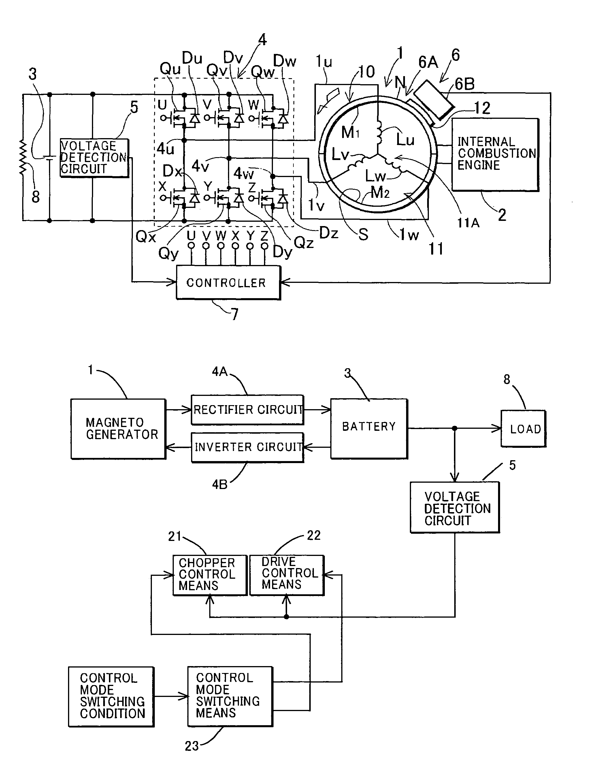
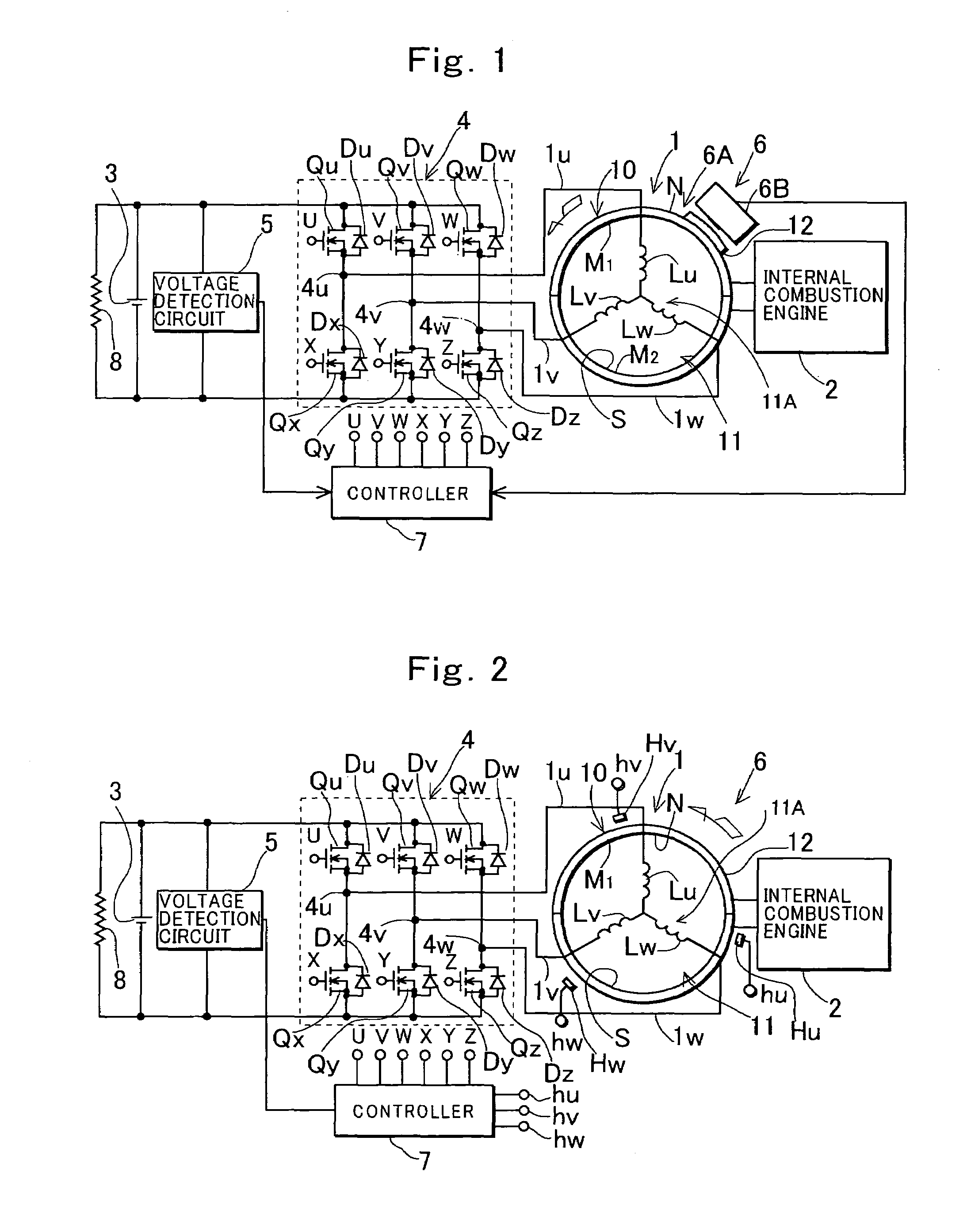
[0047]FIG. 1 shows an entire construction of an embodiment in which the invention is applied to a generating device that uses a magneto generator having a stator with a three-phase armature coil to charge a battery. In FIG. 1, a reference numeral 1 denotes a magneto generator driven by an internal combustion engine 2, and 3 denotes a battery. A reference numeral 4 denotes an AC / DC conversion unit provided between the magneto generator 1 and the battery 3, which has a rectifier and an inverter circuit. A reference numeral 5 denotes a voltage detection circuit that detects a voltage output from the magneto generator 1 through the rectifier circuit in the conversion unit 4 (a voltage across the battery), and 6 denotes a signal generating device that generates pulses when a rotational angle position of a magnet rotor of the magneto generator 1 matches a predetermined position. A reference numeral 7 denotes a controller having a microprocessor, and 8 denotes a load connected across the b...
second embodiment
[0112]As described above, when the control mode is switched from the chopper control mode to the drive control mode, the charging current is estimated from the duty ratio of the chopper control to arithmetically operate the initial value of the phase angle of the AC control voltage of the drive control required for passing the charging current equal to the estimated charging current, while when the control mode is switched from the drive control mode to the chopper control mode, the charging current is estimated from the phase angle of the AC control voltage of the drive control to arithmetically operate the initial value of the duty ratio of the chopper control required for passing the charging current equal to the estimated charging current. This eliminates the need for providing a current detection circuit that detects the charging current of the battery when the voltage across the battery (the output voltage of the generator) is detected to control to keep the detected voltage a...
third embodiment
[0125]In a third embodiment of the invention, control mode switching means 23 is comprised so as to switch the control mode to the drive control mode when the rotational speed becomes higher than the set speed, the output of the magneto generator 1 becomes lower than a set value, and the duty ratio of the chopper control reaches a value that maximizes the output current of the magneto generator 1, in a state where the rotational speed of the magneto generator 1 is lower than the set speed N1 in the control by the chopper control mode, and to switch the control mode to the chopper control mode when the rotational speed becomes lower than the set speed N1, the output of the magneto generator becomes lower than the set value, and the phase angle of the AC control voltage reaches a value that maximizes the output current of the magneto generator, in a state where the rotational speed is the set speed or higher in the control by the drive control mode.
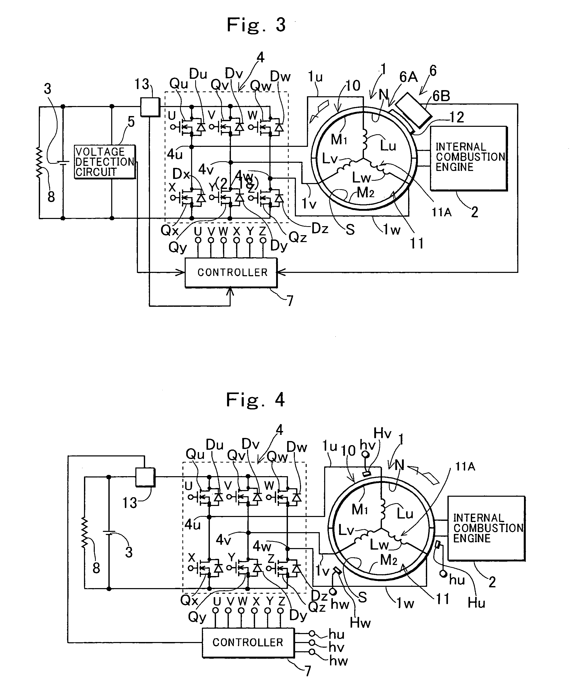
[0126]FIG. 8 shows a construction ex...
PUM
 Abstract
Description
Claims
Application Information
 - R&D
- Intellectual Property
- Life Sciences
- Materials
- Tech Scout
- Unparalleled Data Quality
- Higher Quality Content
- 60% Fewer Hallucinations
Browse by: Latest US Patents, China's latest patents, Technical Efficacy Thesaurus, Application Domain, Technology Topic, Popular Technical Reports.
© 2025 PatSnap. All rights reserved.Legal|Privacy policy|Modern Slavery Act Transparency Statement|Sitemap|About US| Contact US: help@patsnap.com


