Methods and apparatus for self-inverting turbo code interleaving with high separation and dispersion

a turbo code and interleaving technology, applied in the field of self-inverting interleavers/deinterleavers, can solve the problems of low dispersion of this interleaver, poor performance in practice, and the performance of block interleavers is markedly inferior in turbo coding applications, so as to reduce the impact of errors, high dispersion, and high separation

Active Publication Date: 2006-07-25
TEXAS INSTR INC
View PDF4 Cites 2 Cited by
  • Summary
  • Abstract
  • Description
  • Claims
  • Application Information

AI Technical Summary

Benefits of technology

[0019]The present invention satisfies the above-stated needs and overcomes the above-stated and other deficiencies of the related art by providing methods, systems and apparatus for reducing the impact of errors in digital communications systems through the use of self-inverting interleavers / de-interleavers. In particular, the present invention is directed to self-inverting interleaving in which both high separation and high dispersion are achieved. The present invention offers the possibility of nearly halving the amount of necessary circuitry to perform interleaving and de-interleaving functions in a turbo code system. For example, significant advantages are achieved in that one physical implementation of dual-function circuitry can be utilized to perform both interleaving and de-interleaving functions. This eliminates the need of the prior art to provide separate circuitry to perform each of these functions independently and, thereby, reduces the amount of necessary circuitry by nearly fifty percent.
[0020]The present invention stems from the realization that there is often little correspondence between the simplicity / complexity of a mathematical function and the actual complexity of the circuitry necessary to implement that function. Ideally, interleaver / de-interleaver designs in accordance with the present invention should have high separation and dispersion, and, in addition, should be easy to implement. Thus, the present invention lends design primacy to the goal of reducing circuit complexity rather than striving for concise mathematical expressions. For example, the present invention enables a large gate savings (by a factor of 2 or more) in the interleaver implementation.

Problems solved by technology

Nonetheless, the dispersion of this interleaver is so low that it gives poor performance in practice.
Furthermore, it is known that block interleavers give markedly inferior performance in turbo coding applications because such interleavers are subject to a significant “error floor” problem, in which error probability decays very slowly with increasing signal to noise ratio beyond a given point.
This too is a major reason for the poor performance of such block interleavers.
Interleavers with good properties for some applications do not necessarily work well in the turbo coding framework.
None of the related prior art interleavers simultaneously offer he qualities of high separation, large dispersion and self-inversion.
For many applications, such as a turbo coding chip, the processing of algorithmic instructions with interleaver circuitry is either not feasible or itself consumes excessive resources.
One significant deficiency associated with most conventional interleavers is that they result in considerable circuit complexity when physically implemented in a communications system.
Naturally, this complexity also increases the cost of implementing an effective interleaver.
In part, this difficulty arises from the fact that conventional interleaver design often starts with the derivation of an elegant mathematical formula, and then seeks a circuit design to implement that formula.
Too often, this approach results in a complicated, inefficient and expensive circuit despite the fact that it may perform in accordance with a relatively simple and elegant mathematical formula.
This problem is further exacerbated by the fact that, for each interleaver designed and implemented, a compatible de-interleaver must also be designed and implemented to reverse the interleaving process during use of a given system.
Thus, the negative impact of relying on unnecessarily complex circuitry is typically two-fold.

Method used


Image

  • Methods and apparatus for self-inverting turbo code interleaving with high separation and dispersion
  • Methods and apparatus for self-inverting turbo code interleaving with high separation and dispersion
  • Methods and apparatus for self-inverting turbo code interleaving with high separation and dispersion

Examples


Embodiment Construction

[0047]The ensuing detailed description provides exemplary embodiments only, and is not intended to limit the scope, applicability, or configuration of the invention. Rather, the ensuing detailed description of the exemplary embodiments will provide those skilled in the art with an enabling description for implementing an embodiment of the invention. It should be understood that various changes may be made in the function and arrangement of elements without departing from the spirit and scope of the invention as set forth in the appended claims.

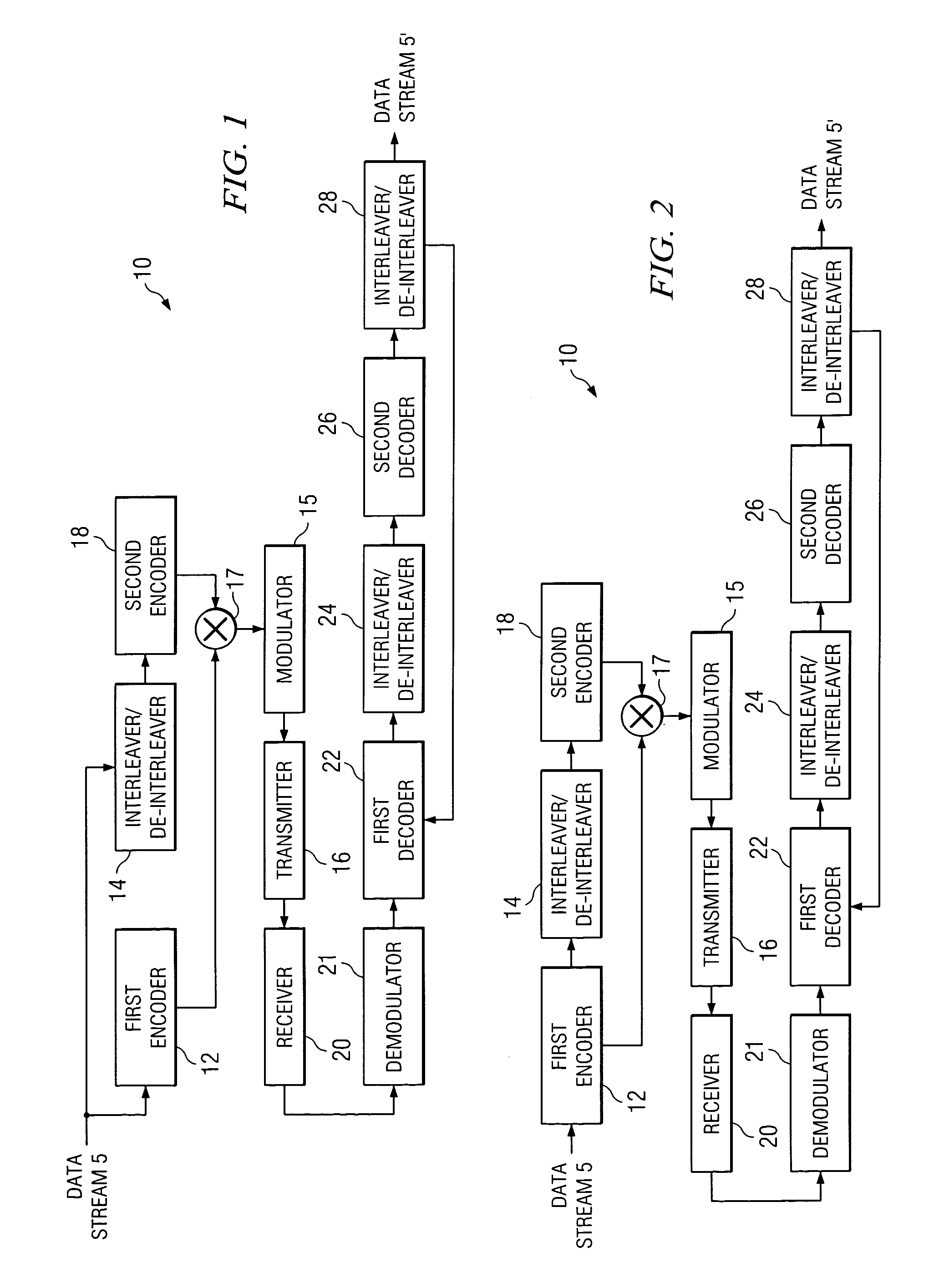
[0048]FIG. 1 shows an example embodiment of a communication system 10 in accordance with the invention which utilizes a parallel encoding scheme. Data stream 5 is split to provide parallel inputs into the system 10. The data stream 5 is encoded at encoder 12 with a first recursive convolutional code to create a first convolutionally coded data stream. Simultaneously, the data stream 5 is interleaved at interleaver / de-interleaver 14 using a sel...


PUM


Abstract

The present invention provides methods for generating self-inverting turbo code interleavers having high separation and high dispersion characteristics. Methods are provided for deterministically generating self-inverting turbo code interleavers from a specification for an existing non-self-inverting interleaver. Methods are also provided for randomly generating self-inverting turbo code interleavers. The present invention also provides methods and apparatus for encoding digital data and communicating the digital data using self-inverting turbo code interleavers / de-interleavers.

Description

[0001]This application claims the benefit of U.S. provisional patent application No. 60 / 382,493 filed on May 21, 2002, which is incorporated herein and made a part hereof by reference.BACKGROUND OF THE INVENTION[0002]1. Field of the Invention[0003]The present invention is directed to digital communications systems, processes, apparatus and related software utilizing error-correcting codes. More particularly, the invention relates to self-inverting interleavers / de-interleavers for use with wireless communication systems that rely on turbo codes to perform signal error-correction. Accordingly, the general objects of the invention are to provide novel systems, methods, apparatus and software of such character.[0004]2. Description of the Related Art[0005]The field of error control coding was revolutionized in 1993 with the invention of turbo codes. With the use of turbo codes, it is possible to achieve extremely low error probabilities at low signal to noise ratios with decoding circuit...

Claims


Application Information

Patent Timeline
Patent Type & Authority Patents(United States)
IPC IPC(8): H04L23/02H04L1/00
CPCH04L1/0066H04L1/005
Inventor COFFEY, JOHN T.HEEGARD, CHRIS
Owner TEXAS INSTR INC
Why Eureka
Try Eureka