Method for measuring the rotational speed of a crankshaft

a technology of crankshaft and rotational speed, which is applied in the direction of instruments, electrical control, force/torque/work measurement apparatus, etc., can solve the problems of weak averaging in this range, and achieve the effect of reducing the difficulty of adjusting the calculation, and improving the accuracy of the calculation

Inactive Publication Date: 2006-07-25
ROBERT BOSCH GMBH
View PDF2 Cites 3 Cited by
  • Summary
  • Abstract
  • Description
  • Claims
  • Application Information

AI Technical Summary

Benefits of technology

[0007]The function of averaging via a variable number of teeth is carried out on the function level in the time grid using the user layer of the control unit. This represents a resource-saving alternative to the complex approach on the TPU level. Therefore, the method according to the present invention may be implemented relatively inexpensively. A comparable implementation of the method according to the present invention on the TPU level (hardware module of the control unit) would, in contrast, require comparatively high expenditures.
[0008]According to a refinement of the method according to the present invention, the number of markings situated between the two markings increases with increasing rotational speed. At a low rotational speed, the error is dominating due to the dynamics, thereby making weak averaging in this range necessary. At a high rotational speed, the dynamic effect is weakened, while the tolerances of the sensor wheel (sensor disk) gain in importance. Therefore, averaging based on a larger number of teeth is sensible in this range.

Problems solved by technology

At a low rotational speed, the error is dominating due to the dynamics, thereby making weak averaging in this range necessary.

Method used


Image

  • Method for measuring the rotational speed of a crankshaft
  • Method for measuring the rotational speed of a crankshaft

Examples


Embodiment Construction

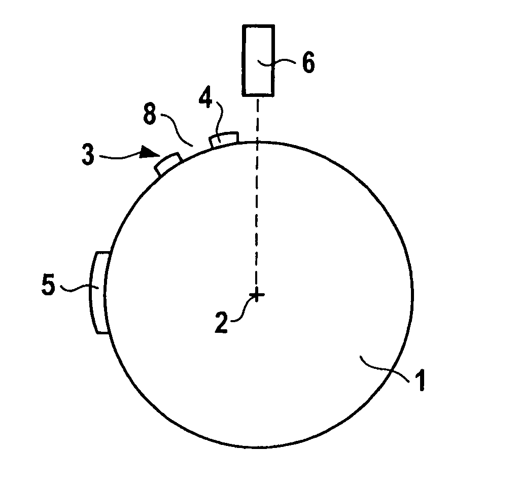
[0016]FIG. 1 shows a diagram of a sensor disk 1 which, for example, is situated directly on a crankshaft or a camshaft or is indirectly connected to the crankshaft or camshaft via transmission elements with regard to the rotation. Sensor disk 1 rotates around an axis2. Markings 3 are situated on the outer circumference of sensor disk 1. The markings are composed of teeth 4, for example, which are each situated equidistant over the outer circumference of sensor disk 1. Tooth spaces 8 are situated between teeth 4. An additional marking 5, e.g., as shown here in the form of a double-width tooth 4 or in form of a larger tooth space between teeth 4 or the like, marks a designated zero position of the crankshaft or camshaft. A sensor 6 is situated on sensor disk 1.

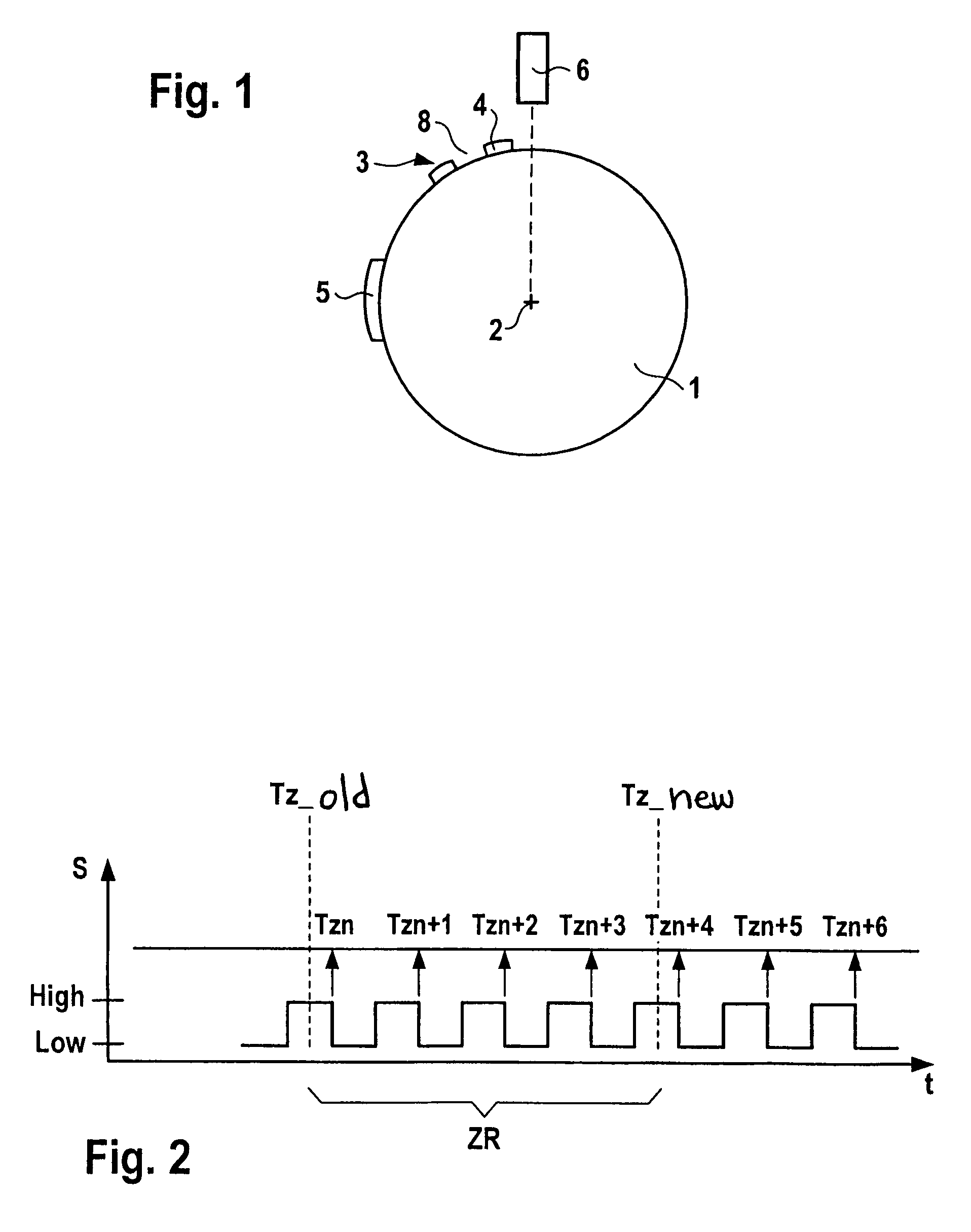
[0017]During a rotation of the camshaft and thus sensor disk 1, teeth 4 and marking 5 are moved past sensor 6, thereby triggering an electrical signal in sensor 6, for example. Sensor 6 may be an inductive, a capacitive, or a Ha...


PUM


Abstract

In a method for determining the rotational speed of the crankshaft of an internal combustion engine having a sensor disk which is connected to a crankshaft of the internal combustion engine, the sensor disk having a marking via a system of alternating teeth and tooth spaces, and a first sensor assigned to the sensor disk generating an electrical signal which is able to assume at least two signal levels, one of the signal levels being assigned to a tooth and the other being assigned to a tooth space, the accuracy of the rotational speed determination is increased in that the rotational speed of the crankshaft is determined by the control unit from the angle between two markings divided by the time elapsed between the two markings; additional markings may be situated between the two markings and the number of markings which are situated between the two markings is a function of the rotational speed.

Description

FIELD OF THE INVENTION[0001]The present invention relates to a method for determining the rotational speed of the crankshaft of an internal combustion engine having a sensor disk which is connected to a crankshaft of the engine, the sensor disk having a marking via a system of alternating teeth and tooth spaces, and a sensor assigned to the sensor disk generating a signal which is able to assume two signal levels, one signal level being assigned to a tooth and the other signal level being assigned to a tooth space, as well as a control unit for carrying out the method.BACKGROUND INFORMATION[0002]The rotational speed for the timer processor unit (TPU) level is determined in two different ways according to the related art. First, the TPU calculates the rotational speed based on the last tooth time and second, the TPU receives a tooth time from the functional level of the control unit. The tooth time is calculated based on the segment time. In an internal combustion engine having six c...

Claims


Application Information

Patent Timeline
Patent Type & Authority Patents(United States)
IPC IPC(8): F02D41/00F02D45/00
CPCG01P3/489F02D41/0097
Inventor BAUMANN, ANDREASWENZLER, THOMASCREPIN, PIERRE-YVES
Owner ROBERT BOSCH GMBH
Why Eureka
Try Eureka