
Device for irradiating tissue

a tissue irradiation and tissue technology, applied in the field of optical devices, can solve the problems of high cost and complexity, substantial repair or replacement costs, and partially or fully inoperativeness, and achieve the effects of reducing tissue thermal damage, less prone to malfunction, and manufacturing cheaply

Inactive Publication Date: 2006-08-01
BOSTON SCI SCIMED INC
View PDF28 Cites 104 Cited by
  • Summary
  • Abstract
  • Description
  • Claims
  • Application Information

AI Technical Summary

Benefits of technology

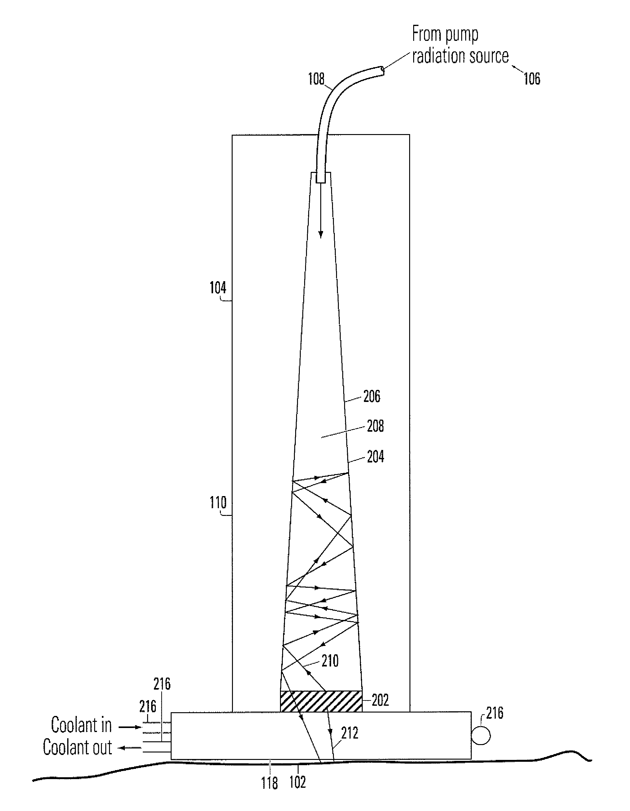
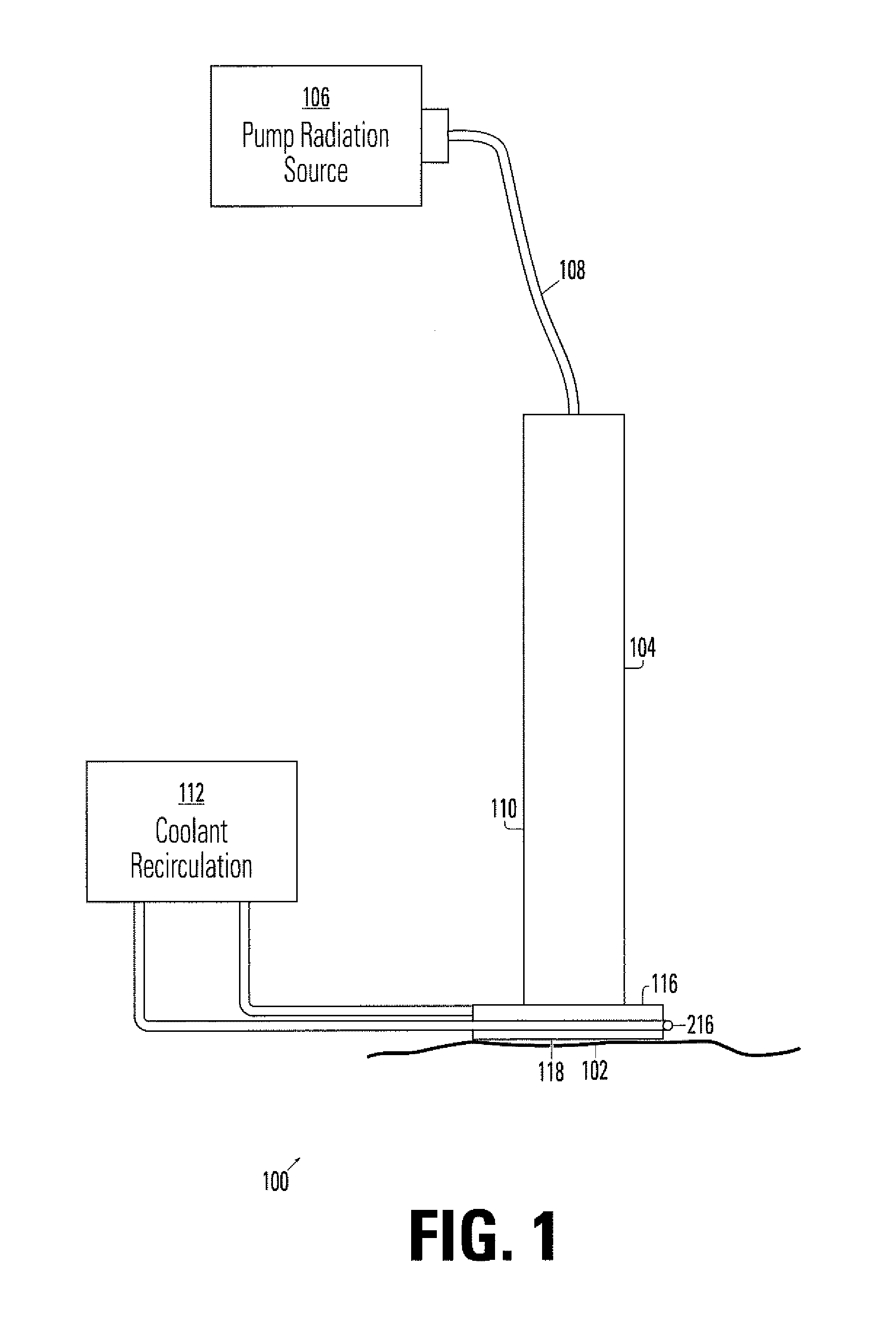
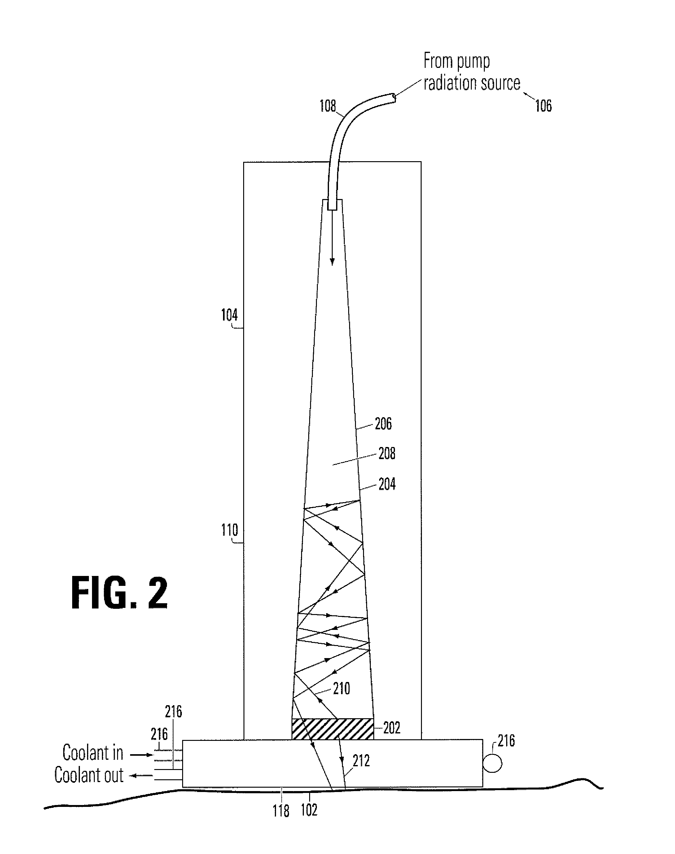
The invention provides a device for irradiating tissue that uses a fluorescent element to receive pump radiation and emit diffuse radiation with different spectral characteristics. The device has a redirector to direct the emitted radiation towards the tissue target. The device can be used for various medical procedures, such as selective photothermolysis, tattoo removal, wrinkle treatment, and PDT. Compared to prior art systems, the device is cheaper, less prone to malfunction, and easier to use. The technical effects of the invention are improved tissue irradiation with reduced risk of thermal damage and improved efficiency of the treatment procedure.

Problems solved by technology

Disadvantages associated with dye lasers include their high expense and complexity.
Misalignment of or damage to optical components, malfunctioning of the dye recirculation system, and / or problems with control circuitry may cause the tunable dye laser to become partially or fully inoperative, leading to downtime and substantial repair or replacement costs.
Further, owing to their relative complexity, it may be necessary to provide extensive training and practice to clinicians before they are able to competently operate dye laser-based systems.

Method used


Image

  • Device for irradiating tissue
  • Device for irradiating tissue
  • Device for irradiating tissue

Examples


second embodiment

[0028]FIG. 4 depicts a device 400 for irradiating tissue 102. The device housing has been omitted in FIG. 4 for the purpose of clarity. Device 400 is provided with a fluorescent element 402 and window 404 of similar description to fluorescent element 202 and window 116 of the FIG. 2 embodiment. Redirector 406 consists essentially of a mirror 408 having a coating 410 which selectively reflects wavelengths corresponding to the radiation emitted by fluorescent element 402 while being substantially transparent to wavelengths corresponding to the pump radiation. Coating 410 may conventionally comprise a plurality of dielectric layers, the number, thicknesses, and composition of dielectric layers being chosen to produce the desired selective reflectance behavior. As indicated by ray 412, radiation emitted by fluorescent device 402 in a non-preferred direction (away from tissue target 102) is reflected by coating 410 and thereby redirected toward tissue target 102. Window 404 may be provid...

third embodiment

[0030]FIG. 6(a) is a cross-sectional view of a device 600 for irradiating tissue 102 according to the invention. Device 600 is provided with a fluorescent element 602 and window 604 of similar description to fluorescent element 202 and window 116 of the FIG. 2 embodiment. Redirector 606 comprises a waveguide 608 having a reflective entrance face 610 and reflective walls 612 extending from entrance face 610 to fluorescent element 602. The core of waveguide 608 may be fabricated from glass, sapphire or other suitable high refraction index material. Referring to FIG. 6(b), which shows a top plan view of entrance face 610, it is seen that entrance face 610 includes a central aperture 614 through which pump radiation from radiation source 106 is admitted into waveguide 608. Central aperture 614 is configured to be substantially transparent in the wavelength(s) of the pump radiation. Device 600 may include a divergent lens or similar element 616 positioned between the end of optical fiber...


PUM


Abstract

A device for irradiating tissue includes a fluorescent element for receiving pump radiation and responsively emitting radiation having different spectral characteristics than the pump radiation. A redirector receives emitted radiation promulgated in a direction away from a tissue target and redirects the radiation toward the target. The pump radiation may be supplied, for example, by a flashlamp or frequency-doubled neodymium-doped laser. Use of the device provides an inexpensive and effective alternative to conventional dye laser-based systems for various medical therapies, including treatment of vascular and pigmented lesions, tattoo and hair removal, and photodynamic therapy (PDT).

Description

FIELD OF THE INVENTION[0001]The present invention relates generally to optical devices, and more particularly to devices for irradiating tissue for use in medical procedures.BACKGROUND OF THE ART[0002]A variety of medical procedures utilize a laser or other radiation source to irradiate a tissue target. Examples of such procedures include dermatological therapies such as treatment of vascular lesions and removal of tattoos and unwanted hair, as well as non-dermatological procedures such as photodynamic therapy (PDT) for treatment of tumors. In procedures involving irradiation of a tissue target, it is usually desirable to match the spectral characteristics of the light produced by the radiation source with the absorption characteristics of the target. This matching promotes efficient absorption of the radiation by the target (which is necessary to effect the localized heating or ablation of the target) and may minimize thermal damage to adjacent tissue.[0003]To facilitate matching o...

Claims


Application Information

Patent Timeline
Patent Type & Authority Patents(United States)
IPC IPC(8): A61B18/18
CPCA61B18/203A61B2018/00005A61B2018/00452A61N5/062A61B2018/00476A61B2018/2065A61B2018/2255A61B2018/00458A61B18/18A61B2018/1807
Inventor MURRAY, STEVEN C.DAVENPORT, SCOTT A.
Owner BOSTON SCI SCIMED INC
Learn More