Method and apparatus for generating hydro-electric power

Active Publication Date: 2006-08-01
MARTIN GERALD G
View PDF24 Cites 87 Cited by
  • Summary
  • Abstract
  • Description
  • Claims
  • Application Information

AI Technical Summary

Benefits of technology

[0015]The hydroelectric power generating apparatus can be varied with, as described above, with plural inlet pipes and plural outlet pipes. The power generating apparatus can also include flow control valves, a by-pass pipe, a y-strainer, and y-strainer valves. The power generating apparatus can be interconnected with in series with other power generating apparatuses. Various aspects of maintenance of the power generating apparatus can be accomplished through the use of the flow control valves and the by-pass pipe that enable maintenance to be performed. The y-strainer is placed inline above the generator to catch debris and sediment. This can be cleaned on a scheduled maintenance program to keep the power generating apparatus running smoothly. Variations can be made regarding the materials and configurations of the various components of the generating apparatus. The piping sizes can be reduced to reach a desired pressure sufficient to turn the turbine of the turbine generation combination. The piping can be flanged on both sides and bolted together using engineering materials and torque specifications. Deliver ductwork can be buried as it reaches the shore to significantly reduce visual impacts.
[0016]A hydroelectric power generating method provides at least one inlet pipe perpendicular to a flow of water in a stream or river, the at least one inlet pipe having a length and plural apertures along the length of the at least one inlet pipe; interconnects a feedline and a turbine generator combination with the at least one inlet pipe; interconnec

Problems solved by technology

Nuclear power is economical but invol

Method used


Image

  • Method and apparatus for generating hydro-electric power
  • Method and apparatus for generating hydro-electric power
  • Method and apparatus for generating hydro-electric power

Examples


Embodiment Construction

[0022]The present invention is a hydroelectric power generating method and / or apparatus. The invention disclosed herein is, of course, susceptible of embodiment in many different forms. Shown in the drawings and described herein below in detail are preferred embodiments of the invention. It is to be understood, however, that the present disclosure is an exemplification of the principles of the invention and does not limit the invention to the illustrated embodiments.

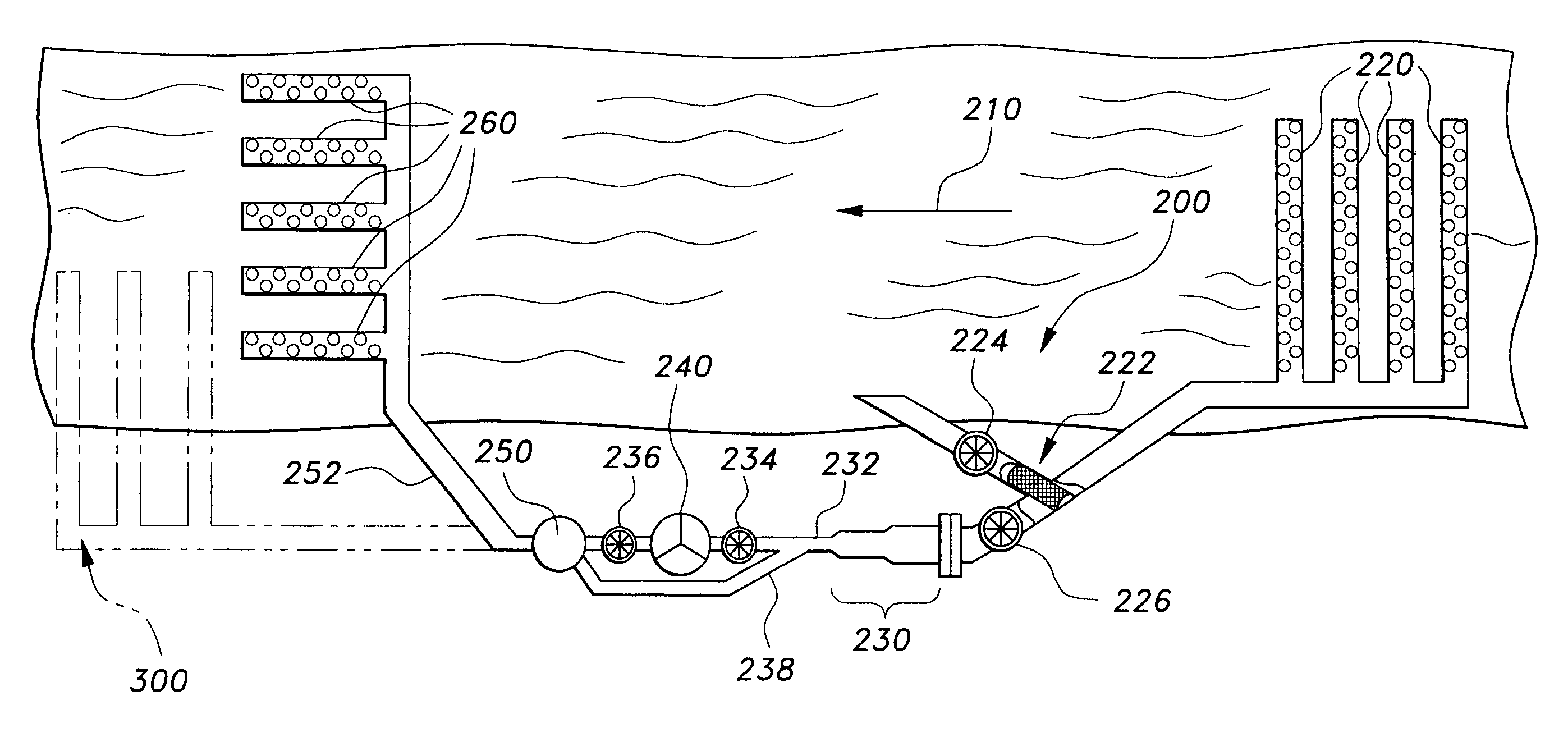
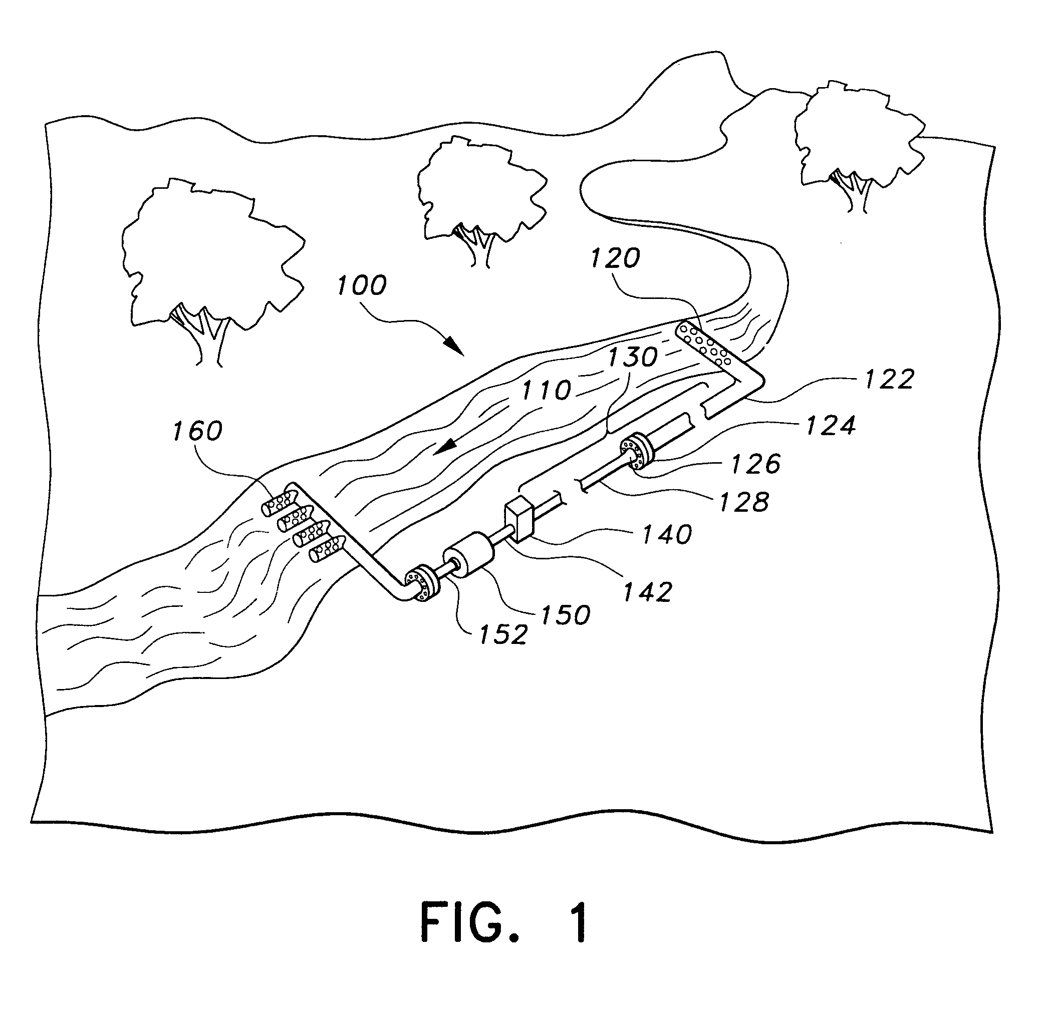
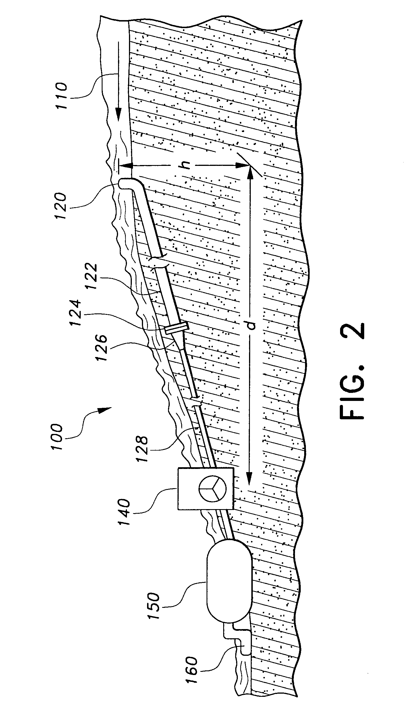
[0023]Referring now to the drawings, FIGS. 1 and 2 show a hydroelectric power generating apparatus 100 according to the invention. The power generating apparatus 100 is configured to pass a portion of a flow of water 110 through an input pipe 120, a feedline 122 configured with funneling of the piping to increase the pressure of the water to a pressure sufficient to turn a turbine of a turbine generator combination 140. The turbine is interconnected with and drives a generator that outputs electrical power. The water tha...


PUM


Abstract

A hydroelectric power generating method and/or apparatus provides one or more inlet pipes perpendicular to a flow of water in a stream or river. The inlet pipes have a length and plural apertures along the length of the at least one inlet pipe. A feedline and a turbine generator combination are interconnected with the inlet pipes. One or more outlet pipes are interconnected with the feedline and the turbine generator combination. The outlet pipes have an elevation lower than the inlet pipe. A flow of water passes through the inlet pipes, the feedline, the turbine generator combination, and the outlet pipes, and generates electricity from the flow of water passing through the turbine generator combination. The hydroelectric power generating method also provides a pressure dissipation device that causes a reduction in the pressure of the water so that the water can be released safely back into the stream or river.

Description

CROSS-REFERENCE TO RELATED APPLICATION[0001]This application claims the benefit of U.S. Provisional Patent Application Ser. No. 60 / 653,515, filed Feb. 17, 2005.BACKGROUND OF THE INVENTION[0002]1. Field of the Invention[0003]The present invention relates generally to electric power generation and, more particularly to a hydroelectric power generating method and apparatus.[0004]2. Description of the Related Art[0005]The constant increase in demand for electric power has resulted in various sources of electric power. Coal fired electric plants strip the land and make large pits. Nuclear power is economical but involves environmental and variable issues. Hydroelectric power is a renewable source but has some environmental and ecological effects. Typical hydroelectric power is generated through the use of dams that feed turbines and turns them for power generation. Building additional dams requires environmental and ecological studies, not to mention political questions. Turbines are bas...

Claims


Application Information

Patent Timeline
IPC IPC(8): F03B13/00
CPCF03B13/086F03B17/06Y02E10/28Y02E10/22Y02E10/20Y02E10/30
Inventor MARTIN, GERALD G.
Owner MARTIN GERALD G
Why Eureka
Try Eureka