

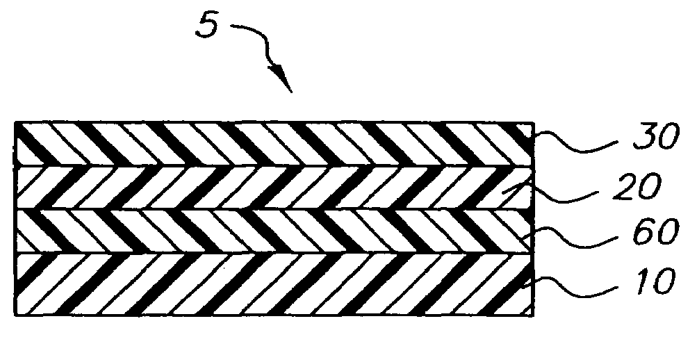
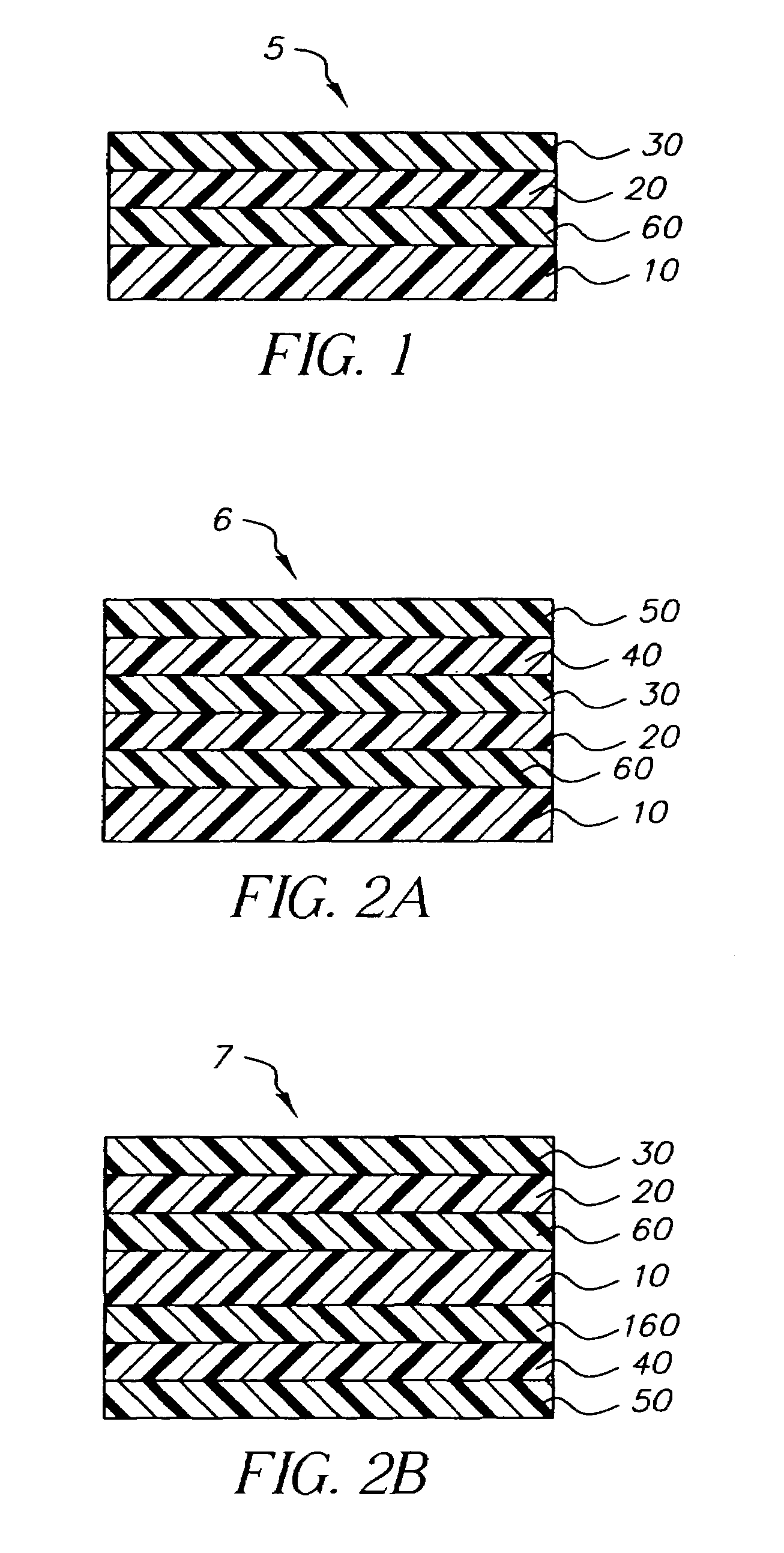
Compensator having particular sequence of films and crosslinked barrier layer
a technology of optical compensators and films, applied in optics, instruments, polarising elements, etc., can solve the problems of narrow viewing angle problems in typical twisted nematic liquid crystal displays, light, color or hue shifts with associated degradation of color reproduction, etc., and achieve the effect of widening the viewing angle characteristics of liquid crystal displays
- Summary
- Abstract
- Description
- Claims
- Application Information
AI Technical Summary
Benefits of technology
Problems solved by technology
Method used
Image

Examples
example 1
[0052]A coating solution of the following composition containing Cymel 300 was coated on 127 micron thick triacetyl cellulose to create a barrier layer using an extrusion hopper. PTSA was used as the acid catalyst to crosslink the Cymel 300 coating. The coated layer was dried and crosslinked at 115° C. for 2 minutes to form a transparent barrier layer having a dried weight of 3.23 g / m2.
[0053]
Methanol44.13%Butanol10.54%Cymel 30033.33%PTSA (10% solution in methanol) 12%
(LPP Orientation Layer)
[0054]On top of the crosslinked Cymel 300 polymer layer a photoalignment layer was coated from the following solution at a wet coverage of 16.5 g / m2. After drying to remove solvents, the sample was exposed to linearly polarized UVB light at a 20 degree angle.
[0055]
Staralign 2110MEK (2% solution)23.30%Methyl ethyl ketone13.95%Cyclohexanone22.75%n-Propyl acetate40.00%
(Optically Anisotropic Layer LCP)
[0056]A solution of a diacrylate nematic liquid crystal material, CB483(MEK) of the f...
examples 2 – 4
Examples 2–4
[0061]The following resins were spin coated at 1000 rpm on glass plates using water as the coating solvent. The coated layer was dried and crosslinked at 80° C. for 5 minutes to form transparent barrier layers. The orientation and optically anisotropic layers were subsequently coated on the glass plates as described in Example 1 except that they were spin coated at 1000 rpm. The optical compensators thus produced on glass plates were evaluated for contrast as described in Example 1. The results are shown in Table 2.
[0062]
TABLE 2Exam-CrosslinkerplesResin 1 (wt %)Resin 2 (wt %)(wt %)Contrast2Chem Corr 260NeoRez R600CX100Yes(60)(40)(5% of NeoRezR600)3Haloflex HA 260SCX100 (5)Yes4NeoCryl R633 (50)NeoRez R600CX100 (5)Yes(50)
[0063]As Table 2 shows, these polymers tested as barrier layers all showed good contrast and did not produce any adverse effects by compromising the alignment of the optically anisotropic layer.
[0064]The entire contents of the patents and other publication...
PUM
| Property | Measurement | Unit |
|---|---|---|
| thickness | aaaaa | aaaaa |
| angle | aaaaa | aaaaa |
| thick | aaaaa | aaaaa |
Abstract
Description
Claims
Application Information