Method and apparatus for amplifier linearization using adaptive predistortion

a linearization and adaptive technology, applied in the field of wireless communication, can solve the problems of reducing the effective throughput, the generated signal strength, and the effective range, and achieving the effects of more linear gain response, precise and updateable determination of delays, and precise and aggressive adaptive predistortion

Active Publication Date: 2006-08-01
MARVELL ASIA PTE LTD
View PDF34 Cites 95 Cited by
  • Summary
  • Abstract
  • Description
  • Claims
  • Application Information

AI Technical Summary

Benefits of technology

[0014]By finding the matching sample to a self-received sample in the buffer, methods and apparatus according to the present invention permit more precise and updateable determination of the delays involved in the RF modulation and amplification stages of the amplifier and the self-receiver, thus allowing for more precise and agg...

Problems solved by technology

The large PAR characteristic of this transmission signal makes it difficult to use sub-class A RF power amplification without significant back-off due to nonlinear effects of such power amplifiers, which reduces generated signal strength, effective range, and, ultimately utility as a wireless transmission system.
This brings up the effective transmission gain up 2–3 db typical since PAR is compressed, but still does not provide sufficient extended range over non-implementing systems and can indirectly reduce effective throughput in IEEE 802.11a & 802.11g compliant systems, because such systems will reduce transmission rates in an effort to compensate for reception errors in fringe reception environments.
One obstacle to implementing a successful predistortion design with respect to high-speed, high-PAR signal transmission as required by the IEEE 802.11a ...

Method used


Image

  • Method and apparatus for amplifier linearization using adaptive predistortion
  • Method and apparatus for amplifier linearization using adaptive predistortion
  • Method and apparatus for amplifier linearization using adaptive predistortion

Examples


Embodiment Construction

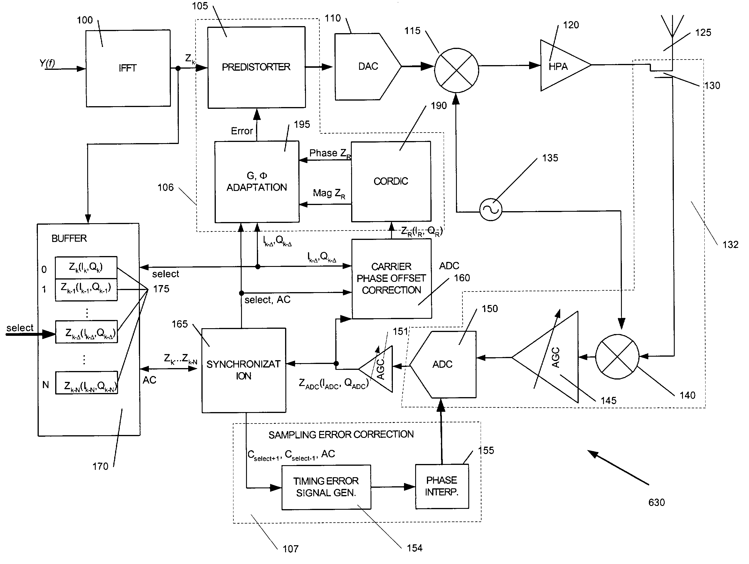
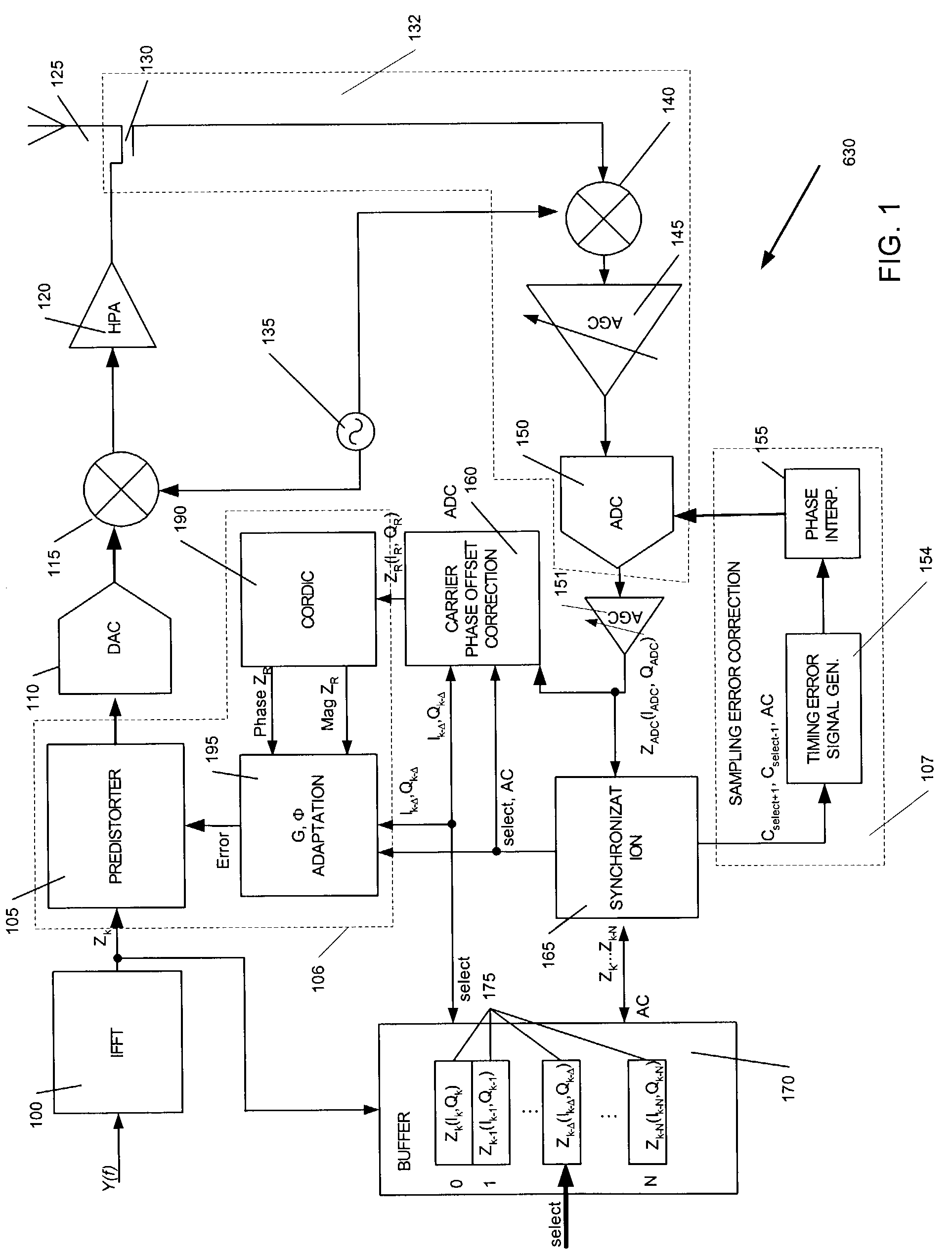
[0024]Turning first to FIG. 1, FIG. 1 depicts a linearizing amplifier 630 according to a first embodiment of the invention. Here, though not required as will be appreciated by those ordinarily skilled in the art, input signal Y(f) is presented as a multi-carrier OFDM-encoded digital signal waveform compliant with IEEE 802.11a (1999) and Draft IEEE 802.11g (2002) transmission rate standards. This input signal Y(f) presents data intended for modulation, amplification and transmission in analog form consistent with these IEEE 802.11a and 802.11g standards.

[0025]An inverse fast Fourier transform (“IFFT”) unit 100 converts the frequency domain input signal Y(f) into a corresponding baseband digital waveform in the time domain as is well known in the art on a per sample basis. As shown in FIG. 1, the output of the IFFT 100 per unit time is shown as complex waveform sample Zk, and referred to generically herein as input signal samples or input samples. Specific input samples processed by t...


PUM


Abstract

A signal processing method and apparatus capable of correcting signal distortion introduced by an RF power amplifier is disclosed, which includes the use of a buffer to store a plurality of samples representing at least a portion of an input signal intended for amplification by the RF power amplifier, the use of a self-receiver to receive an output signal generated by the RF power amplifier, the use of a synchronization unit to determine, as a matching input sample, which of the stored plurality of samples corresponds most closely to the output signal, and the use of a predistortion unit to selectively apply a distortion correction function to the input signal prior to amplification by the RF power amplifier in which the distortion correction function being derived from a relationship between the matching input sample and the output signal. This permits more precise and updateable determination of the delays involved in the RF modulation and amplification stages of the amplifier and the self-receiver, thus allowing for more precise and aggressive adaptive predistortion to be used. A phase offset correction is optionally provided to correct a phase offset in the realized sample of the output signal relative to the matching input symbol. Additionally, a sampling phase error correction unit may be provided to generate sampling alteration information to an analog-to-digital converter to cause such analog-to-digital converter to selectively alter sampling of the output signal.

Description

CROSS-REFERENCE TO RELATED APPLICATIONS[0001]This application claims the benefit of U.S. Provisional Application No. 60 / 357,317, filed on Feb. 15, 2002. The disclosure of the above application is incorporated herein by reference in its entirety.TECHNICAL FIELD[0002]This invention relates to wireless communications, and is particularly concerned with improving amplifier linearization using adaptive predistortion techniques.BACKGROUND OF THE INVENTION[0003]The past few years has witnessed the ever-increasing availability of relatively cheap, low power wireless data communication services, networks and devices, promising near wire speed transmission and reliability. One technology in particular, described in the IEEE Standard 802.11a (1999) and Draft IEEE Standard 802.11g (2002) High Rate PHY Supplements to the ANSI / IEEE Standard 802.11, 1999 edition, collectively incorporated herein fully by reference, has recently been commercialized with the promise of 54 Mbps effective bandwidth in...

Claims


Application Information

Patent Timeline
IPC IPC(8): H04L25/03
CPCH03F1/3247H03F1/3282H04L27/368H03F3/24H03F2200/207H03F2201/3203
Inventor SHIRALI, KEDAR
Owner MARVELL ASIA PTE LTD
Why Eureka
Try Eureka