Gas turbine combustion chamber with defined fuel input for the improvement of the homogeneity of the fuel-air mixture

a combustion chamber and fuel input technology, which is applied in the ignition of turbine/propulsion engines, engine starters, lighting and heating apparatus, etc., can solve the problems of high energy turnover, large fuel mass flows within the combustion chamber, and provide for homogeneous mixing of fuel and passing combustion airflow, so as to achieve cost-effective production and reliable operation

Inactive Publication Date: 2006-08-08
ROLLS ROYCE DEUT LTD & CO KG
View PDF60 Cites 19 Cited by
  • Summary
  • Abstract
  • Description
  • Claims
  • Application Information

AI Technical Summary

Benefits of technology

[0013]It is a broad aspect of the present invention to provide a gas turbine combustion chamber of the type described above which, w...

Problems solved by technology

This calls for high energy turnover and correspondingly large fuel mass flows within the combustion chamber.
In the state of the art, it is disadvantageous that the injection of fuel by means of a central nozzle or a pressure atomizer, respectively, as well as the discharge of fuel in the form of a film on a film applicator will not—or only to a limited extend—provide...

Method used


Image

  • Gas turbine combustion chamber with defined fuel input for the improvement of the homogeneity of the fuel-air mixture
  • Gas turbine combustion chamber with defined fuel input for the improvement of the homogeneity of the fuel-air mixture
  • Gas turbine combustion chamber with defined fuel input for the improvement of the homogeneity of the fuel-air mixture

Examples


Embodiment Construction

[0046]This detailed description should be read in conjunction with the Summary above, which is incorporated by reference in this section.

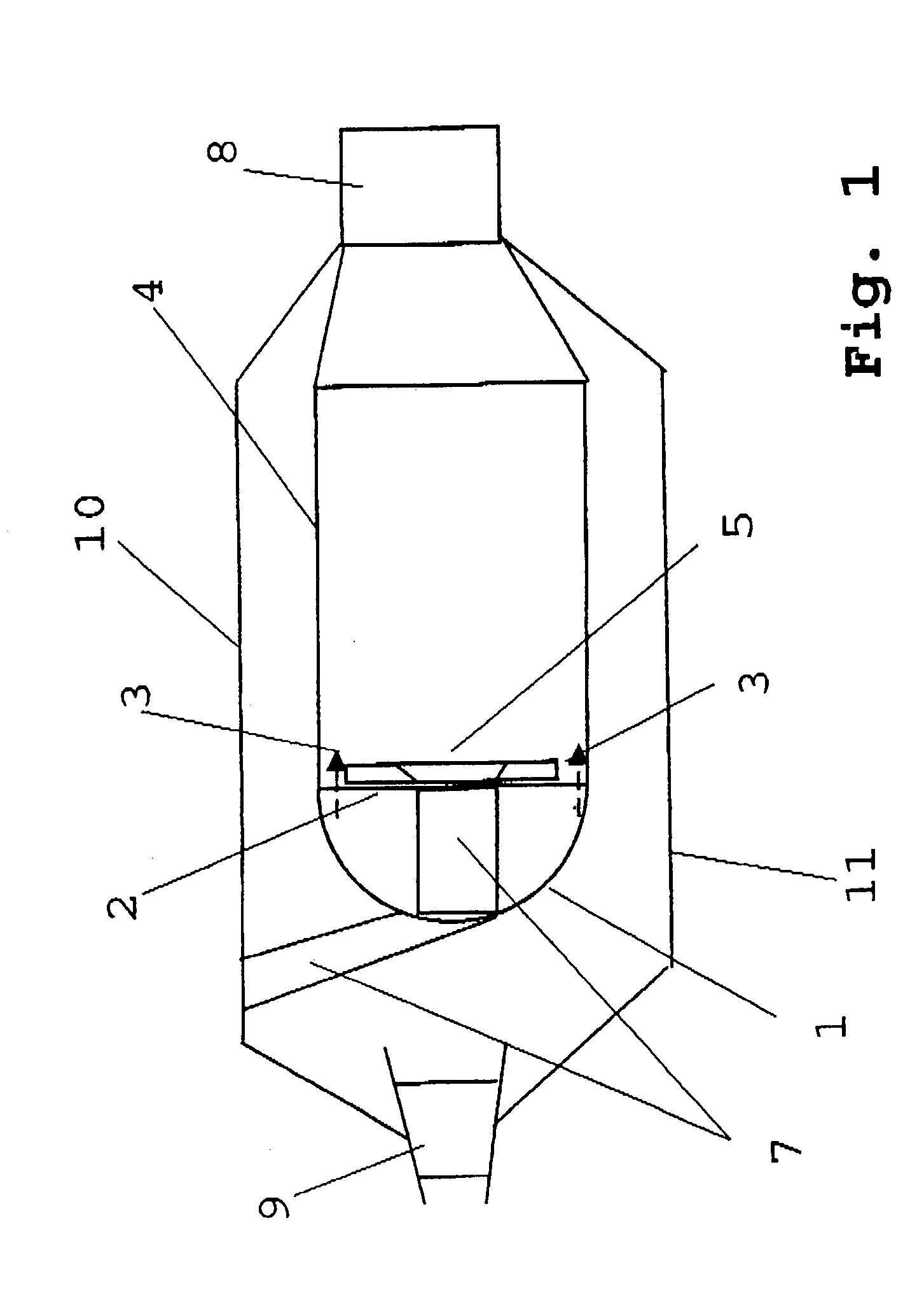
[0047]FIG. 1 shows, in schematic side view, a section through a gas turbine combustion chamber in accordance with the present invention. It comprises a hood 1 of a combustion chamber head and a base plate 2. Further, a combustion chamber wall 4 is shown which connects to a turbine nozzle guide vane 8 shown in schematic representation. FIG. 1 also shows a combustion chamber outer casing 10 and a combustion chamber inner casing 11. In the inflow area, a stator vane 9 of the compressor outlet is shown. Reference numeral 7 shows a burner with burner arm and swirler. Further, the gas turbine combustion chamber comprises a heat shield 5 with a bore for the burner 7 and individual openings for the generation of a starter film 3, these openings not being shown in detail.

[0048]Further details of the gas turbine combustion chamber are dispensed with herein s...


PUM


Abstract

A gas turbine combustion chamber with a burner 7, includes means for the supply of fuel and an atomizer 6, wherein the means for the supply of fuel are provided such that the fuel is injected in areas with maximum airflow velocity.

Description

[0001]This application is a Continuation-In-Part of U.S. patent application Ser. No. 10 / 425,888 (now abandoned) by DORR et al., entitled Gas Turbine Combustion Chamber with Defined Fuel Input for the Improvement of the Homogeneity of the Fuel-Air Mixture, filed Apr. 30, 2003, the entirety of which is incorporated by reference herein.[0002]This application claims priority to German Patent Application DE10219354.1 filed Apr. 30, 2002, the entirety of which is incorporated by reference herein.BACKGROUND OF THE INVENTION[0003]This invention relates to a gas turbine combustion chamber with a burner, with means for the supply of fuel and with an atomizer.[0004]Various forms of gas turbine combustion chambers are known from the state of the art.[0005]For reduction of the pollutant load, in particular nitrogen oxide emissions, the fuel must generally be premixed with as much air as possible to obtain lean combustion, i.e. one characterized by air excess.[0006]In the case of aircraft gas tur...

Claims


Application Information

Patent Timeline
IPC IPC(8): F02C7/22F02C7/26F23R3/14F23R3/28F23R3/30
CPCF23R3/14F23R3/30F23R3/286F23D2900/11101Y02T50/675Y02T50/60
Inventor DOERR, THOMASLAZIK, WALDEMAR
Owner ROLLS ROYCE DEUT LTD & CO KG
Why Eureka
Try Eureka