Refrigerant distribution device and method

a distribution device and refrigeration technology, applied in refrigeration and liquidation, refrigeration machines, lighting and heating apparatus, etc., can solve the problems of complex goal, less than optimal utilization of evaporator heat exchanger, and non-uniform cold air

Active Publication Date: 2006-08-08
LENNOX INTERNATIONAL
View PDF10 Cites 30 Cited by
  • Summary
  • Abstract
  • Description
  • Claims
  • Application Information

AI Technical Summary

Benefits of technology

[0015]One object of the invention is to provide the heat transfer tubes with a homogeneous mixture of liquid and vapor refrigerant which will provide uniform feeding of refrigerant. The result will be uniform utilization of the evaporator heat exchanger.
[0020]Each small diameter nozzle has a vapor inlet port that lies above the refrigerant liquid-vapor interface. Each capillary liquid nozzle has a liquid inlet port below the refrigerant liquid-vapor interface. Refrigerant flow into the inlet tube and a pressure difference between the inlet tube and the outlet header urge a liquid flow through the capillary liquid nozzles and a vapor flow through the small diameter nozzles. The vapor impinges upon liquid flow to create homogeneous mixture of liquid and vaporous refrigerant to be delivered relatively uniformly through the plurality of tubes for efficient distribution of the refrigerant fluid.

Problems solved by technology

This results in uneven feeding of refrigerant into the heat transfer tubes of the heat exchanger, causing less than optimal utilization of the evaporator heat exchanger.
This goal is complicated by the fact that numerous refrigerant passages may deliver non-uniform cold air.
This phenomenon has complicated the task of distributing refrigerant fluid uniformly inside and along the several refrigerant passages of a refrigerant distribution system.
Another complicating factor is that the more remote the refrigerant is from an inlet side of a system including several refrigerant evaporation passages, the more difficult it is for the liquid refrigerant to flow uniformly.
Conversely, the closer the refrigerant is to the inlet side, the more difficult it is for the liquid refrigerant to flow.
This phenomenon tends to cause an uneven distribution of temperature in the emergent cold air.
One limitation of this approach is that the heat exchanger orientations be such that gravity separates the liquid and vapor.
Additionally, this approach is most suitable for plate-type evaporators and may not function effectively in other types of evaporators.
However, there is a non-uniform refrigerant distribution in each section which impedes efficient utilization of the heat exchanger.

Method used


Image

  • Refrigerant distribution device and method
  • Refrigerant distribution device and method
  • Refrigerant distribution device and method

Examples


Embodiment Construction

)

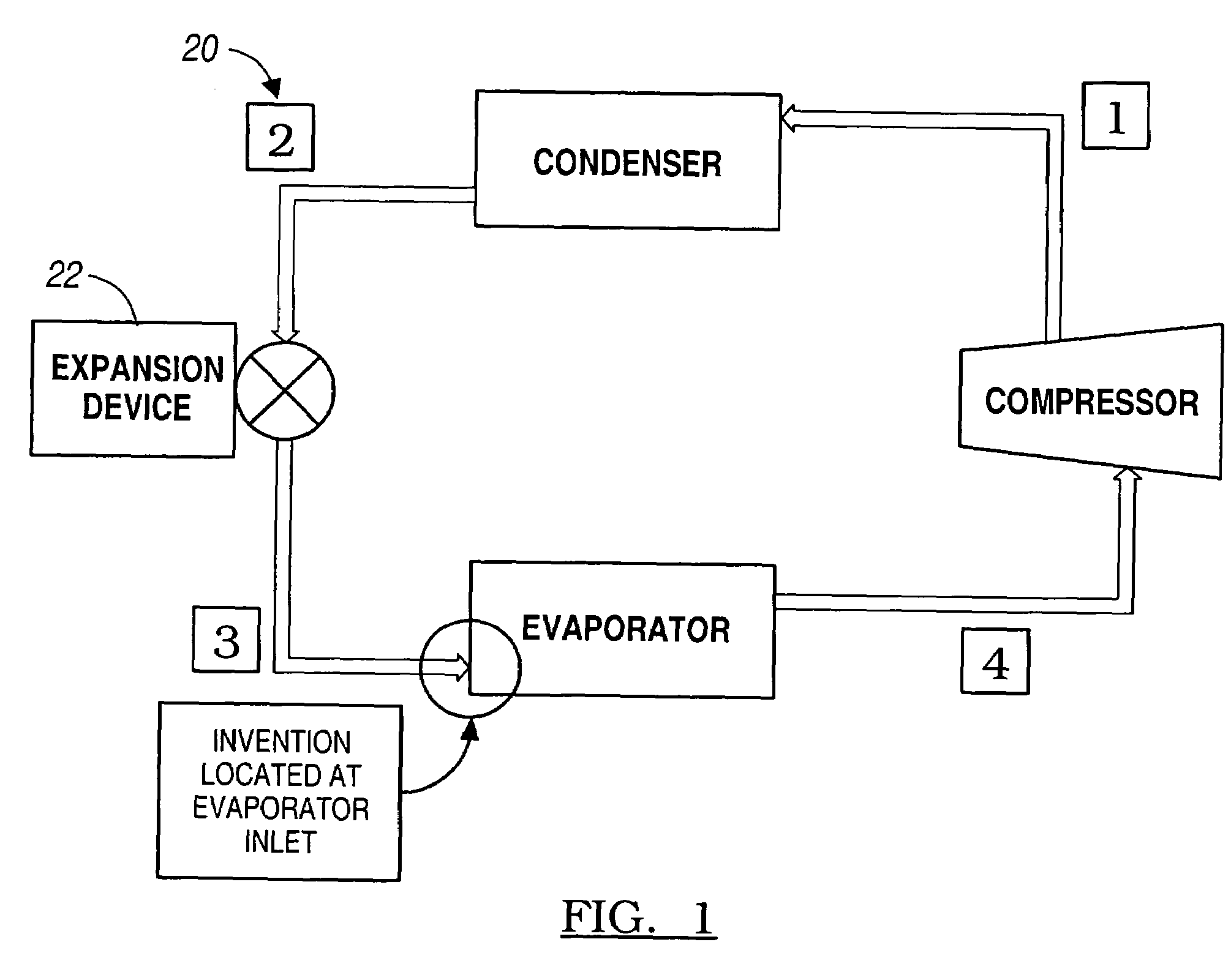
[0025]Turning first to FIG. 1, there are depicted the major components of a conventional refrigeration system. This figure is useful in illustrating the positioning of the invention in relation to conventional components. It will be appreciated that the term “refrigeration cycle” is a generic term which describes a vapor compression cycle that is used in both air conditioning and low temperature refrigeration systems.

[0026]In FIG. 1, the compressor adds energy to a refrigerant by compressing it to a high pressure. The refrigerant enters the condenser along passage (1) as a high temperature vapor. The condenser typically rejects energy to a heat sink—usually ambient air. Upon emergence from the condenser as a high pressure subcooled liquid (2), the refrigerant flows through an expansion (throttling) device. This device reduces the pressure of the refrigerant. On leaving the expansion device, the refrigerant exists in two phases: primarily liquid (about 80%); and some vapor (about 20...


PUM


Abstract

A refrigerant distribution device 10 situated in an inlet header 12 of a multiple tube heat exchanger 14 of a refrigeration system 20. The device 10 includes an inlet passage 32 that is in communication with an expansion device. Small diameter nozzles 34 are disposed within the inlet header 12 and are in fluid communication with the inlet passage 32. Capillary liquid nozzles 36 also lie within the inlet header 12 and are in fluid communication with the inlet passage 32. A two-phase refrigerant fluid in the inlet passage 32 has a refrigerant liquid-vapor interface 38. The vapor nozzles 34 have vapor inlet ports 40 that lie above the refrigerant liquid-vapor interface 38. The capillary liquid nozzles 36 have liquid inlet ports 42 that lie below the refrigerant liquid-vapor interface 38. Vapor emerging from the vapor nozzles 34 blow onto and atomize liquid emerging from the liquid nozzle to create a homogeneous refrigerant that is uniformly delivered to the multiple tubes. The invention also includes a method for delivering a uniform distribution of a homogeneous liquid mixture of liquid and vaporous refrigerant through the heat exchanger tubes.

Description

BACKGROUND OF THE INVENTION[0001]1. Field of the Invention[0002]The present invention relates to a refrigerant distribution device and method for use in a refrigeration system having a compressor, condenser, expansion device, and an evaporator.[0003]2. Background Art[0004]In a typical air conditioning system, high-pressure liquid refrigerant from a condenser enters an expansion device where pressure is reduced. The refrigerant at the exit of the expansion device consists of a mixture of low-pressure refrigerant liquid and vapor. This mixture enters an evaporator where more of the liquid becomes vapor while the refrigerant absorbs energy from the heat exchanger as it cools the air to the conditioned space. In evaporator heat exchangers that are constructed of multiple parallel heat transfer tubes, the incoming refrigerant liquid-vapor mixture typically enters a common manifold that feeds multiple tubes simultaneously.[0005]Due to gravity and momentum effects, the liquid refrigerant s...

Claims


Application Information

Patent Timeline
Patent Type & Authority Patents(United States)
IPC IPC(8): F25B39/02F28F9/02
CPCF25B39/022F28F9/0273F28F9/0265F25B39/028
Inventor BAE, YOUNGLIBHEIDENREICH, MICHAEL E.
Owner LENNOX INTERNATIONAL
Why Eureka
Try Eureka