Facility for the gasification of carbon-containing feed materials

a technology for carbon-containing feed materials and gasification facilities, which is applied in the direction of gasification process details, fuel gas production, combustible gas production, etc., can solve the problems of high-calorie gas production, gas is not suitable for utilization, and energy-related utilization of the abovementioned feed materials, so as to improve the energy balance and improve the energy balance. , the effect of improving the efficiency of the installation

Inactive Publication Date: 2006-08-08
BIOAGE
View PDF13 Cites 13 Cited by
  • Summary
  • Abstract
  • Description
  • Claims
  • Application Information

AI Technical Summary

Benefits of technology

[0016]The particular advantage of the invention consists in that, depending on the adjustment of the pressure conditions, either more gas or more flue gas (heat) can be produced. The desired gas / flue gas ratio is preferably adjusted by means of a flue-gas-regulating arrangement, e.g. by the cross section of the flue-gas-outlet channel being changed, it being possible for this to be achieved by a flue-gas damper.
[0017]In an embodiment of the invention, the fluidized-bed gasification chamber is arranged, in spatial terms, above the filter chamber and the filter chamber is arranged above the combustion chamber. This arrangement results in a very compact construction with a good energy balance.
[0018]In another embodiment of the invention, there is provided an additional heat exchanger, which takes up the waste heat of the drawing-off flue gas and gives it off to the product gas, this likewise improving the energy balance.
[0019]In another embodiment of the invention, heat-exchanger ribs are arranged on the heat-exchanger sections of the heat pipes. These ribs are formed so as to assume an operative relationship with the streams and vortices of fluid produced by the fluidizing arrangements, such that the fluidized particles are accelerated transversely to their original flow direction. It is thus the case that good transverse mixing of the fluidized bed is achieved, the residence time of the particles in the fluidized bed is increased, gas bubbles are well dispersed, and the heat transfer from the heat-exchanger ribs to the fluidized bed is improved to a considerable extent. This also makes it possible to achieve a compact construction.
[0020]A fluidized-bed reactor in accordance with the invention is particularly suitable for use in a facility for producing combustible gas from carbon-containing feed materials according to the present invention. A reactor vessel which accommodates the fluidized bed is provided in the fluidized-bed reactor. Fluidizing arrangements for fluidizing a predetermined region of the fluidized bed are provided. In order for additional heat to be introduced or drawn off in this region, use is made of heat exchangers. The better the heat transfer between the heat exchangers and the fluidized bed, the higher is the efficiency of the installation. In order to improve this heat transfer, the heat-exchanger sections of the heat exchanger are designed as special heat-exchanger ribs which are formed and arranged so as to assume an operative relationship with the streams and vortices of fluid produced by the fluidizing arrangements, such that the fluidized particles are accelerated transversely to their original flow direction, as a result of which the transverse mixing of the fluidized bed is improved, the residence time of the particles in the fluidized bed is increased, and the heat transfer from the heat-exchanger ribs to the fluidized bed is improved to a considerable extent.
[0021]By using such a fluidized-bed reactor, smaller and more cost-effective overall sizes are possible, while maintaining the same output, as a result of the improved heat transfer. Such a fluidized-bed reactor may be used both in the combustion chamber and in the combustible-gas reactor of the facility for producing combustible gas from carbon-containing feed materials.

Problems solved by technology

The energy-related utilization of the abovementioned feed materials, at present, is largely limited to combustion.
These gases, however, are not suitable for utilization, for example, in gas turbines or fuel cells.
This process may also be used to operate relatively small installations cost-effectively, but does not produce any high-calorie gases.
It is barely possible, with the current state of knowledge, to verify that this facility can achieve calorific values of approximately 10 000 kJ / kg.
The use of pulse combustors, however, involves relatively high outlay.
Since the pyrolysis gas mixes with the flue gas, there is a reduction in the calorific value of this gas, which is not suitable for direct use for gas turbines or for fuel cells.

Method used


Image

  • Facility for the gasification of carbon-containing feed materials
  • Facility for the gasification of carbon-containing feed materials
  • Facility for the gasification of carbon-containing feed materials

Examples


Embodiment Construction

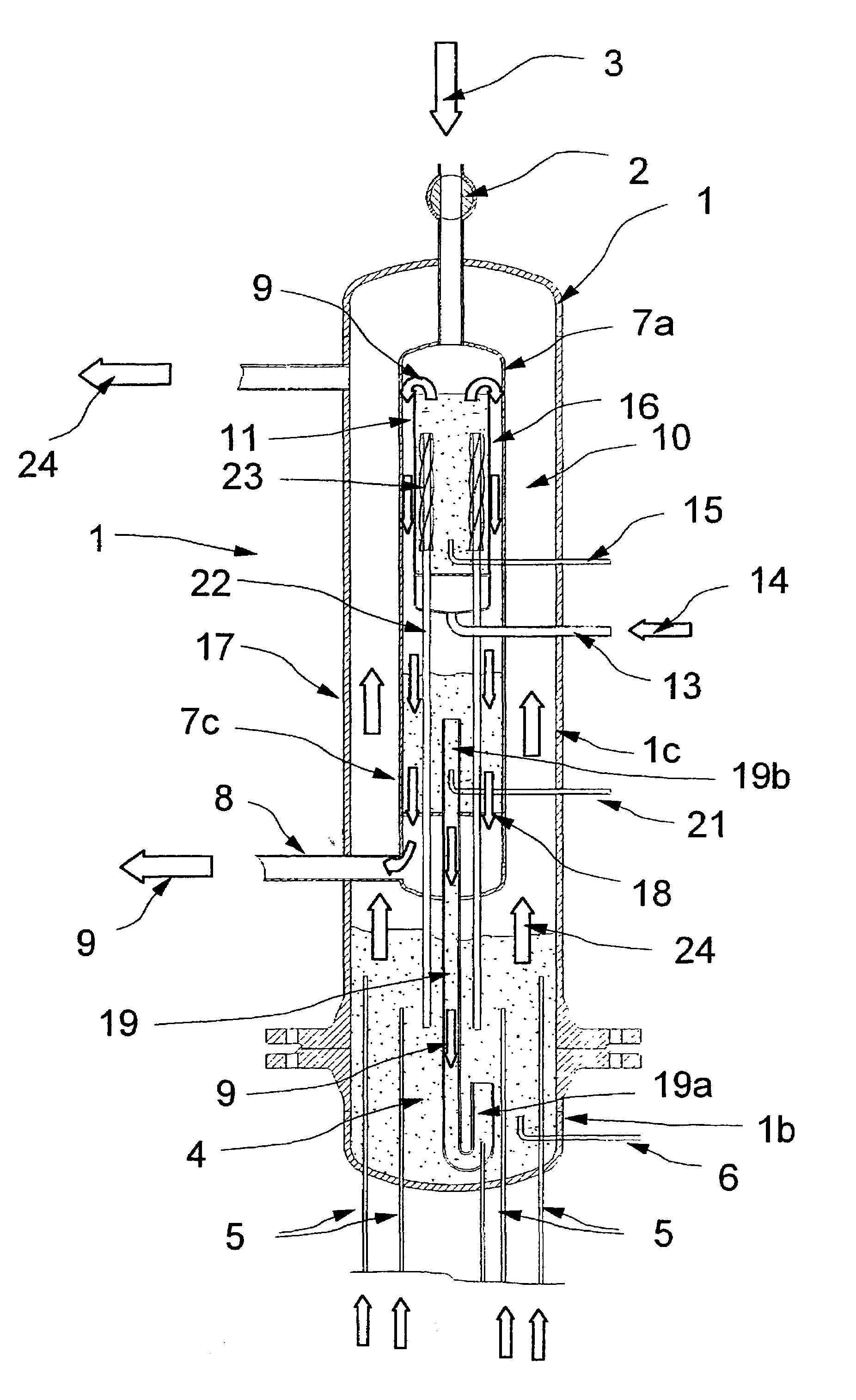
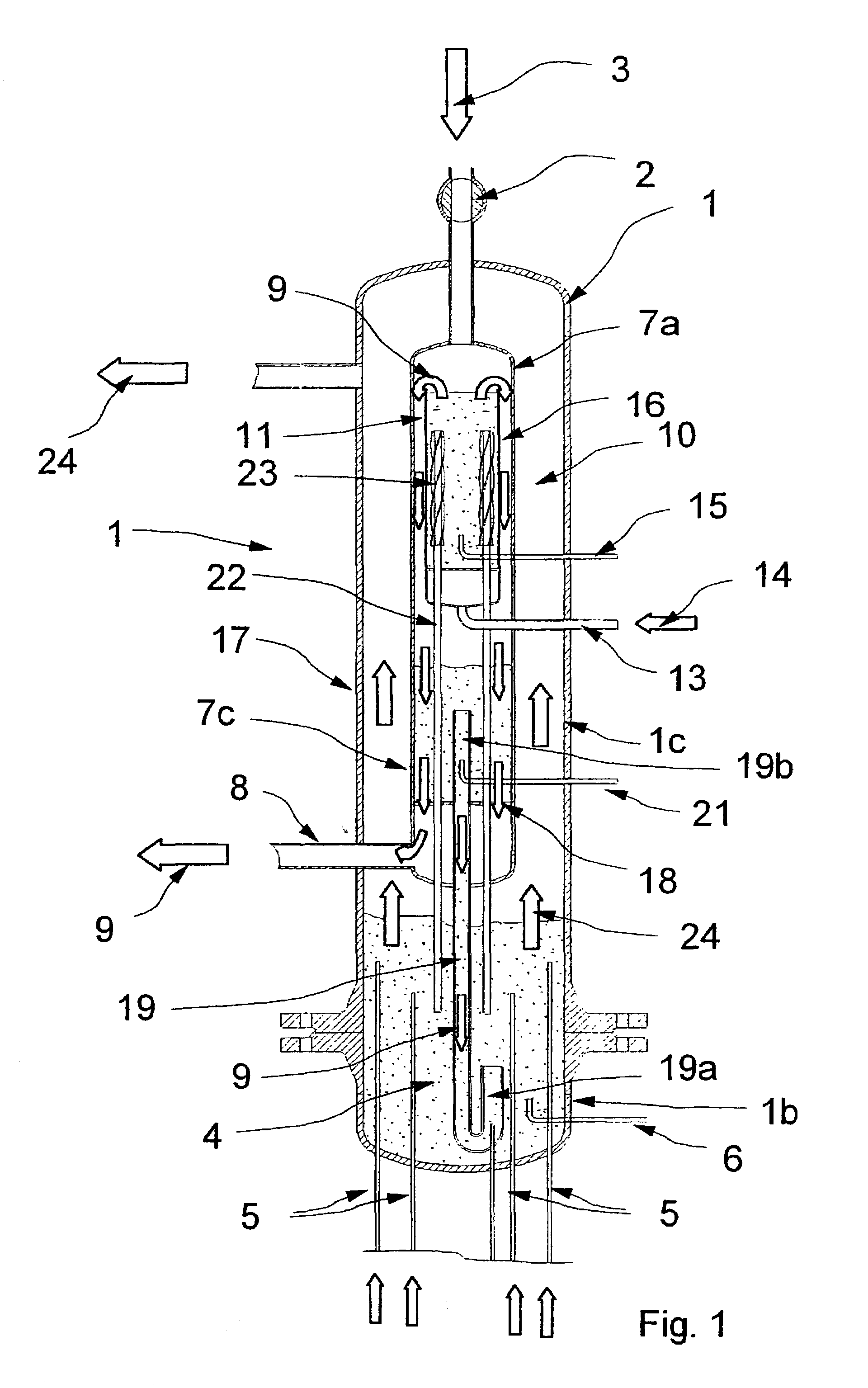
[0034]FIG. 1 shows a first embodiment of the invention. A first tubular vessel 1 has, at its top end section 1a, a pressure-tight lock 2 for introducing the feed materials 3 which are to be gasified, and are illustrated symbolically by means of the arrow. Provided in the bottom end section 1b of the vessel 1 is a fluidized-bed combustion chamber 4, into which steam- and / or air-mixture feed nozzles project. For starting up, i.e. for heating up, a fuel feed nozzle 6 is arranged within the fluidized-bed combustion chamber 4 in order to blow in combustible gas by means of which the fluidized-bed combustion chamber 4 is heated up.

[0035]A second tubular vessel 7 is arranged concentrically in the vessel 1 and extends from the top end section 1a to the fluidized-bed combustion chamber 4. At its top end section 7a, this vessel 7 is connected in a sealed manner to the outlet of the lock 2. Arranged at the bottom end section 7b of the vessel 7 is a combustible-gas outlet 8 for discharging the ...


PUM

PropertyMeasurementUnit
calorific valueaaaaaaaaaa
temperatureaaaaaaaaaa

Abstract

A pressure-supercharged fluidized-bed gasification chamber has a pressure-tight lock for supplying the feed materials which are to be gasified. The fluidized-bed gasification chamber is connected to a filter chamber via a connecting channel, with the result that the gas produced can flow over from the fluidized-bed gasification chamber into the filter chamber, where it is directed through the filter layer. An external heat source provides the necessary heat for the allothermic gasification. A heat-pipe arrangement directs the heat from the external heat source into the gasification bed of the fluidized-bed gasification chamber, in order to provide the temperature which is necessary for the gasification.

Description

BACKGROUND OF THE INVENTION[0001]The invention relates to a facility for the gasification of carbon-containing feed materials, e.g. tar, tar sand, plastics waste, residues from paper and pulp production, residues from the petrochemical industry, electronics scrap and light shredded fractions, and in particular of biogenic feed materials, e.g. harvest waste, energy plants (Mishanthus) or wood chips. The facility serves, in particular, for producing combustible gases with a calorific value of at least 8 000 to 10 000 kJ / m3.[0002]The energy-related utilization of the abovementioned feed materials, at present, is largely limited to combustion. The gasification technologies are set up predominantly for producing weak gases with a calorific value of below 6 000 kJ / kg. These gases, however, are not suitable for utilization, for example, in gas turbines or fuel cells.[0003]In order to produce gases with a calorific value of 8 000 to 10 000 kJ / m3, so-called allothermic gasification has to be...

Claims


Application Information

Patent Timeline
Patent Type & Authority Patents(United States)
IPC IPC(8): C10J3/16B01J8/18B32B5/02F27B5/02B01J8/00B01J8/26B01J8/28B01J8/32C10J3/56F28D15/02
CPCB01J8/006B01J8/26B01J8/28B01J8/32C10J3/482C10J3/503C10J3/56C10K1/024B01J2208/00132C10J2300/1246C10J2200/36B01J2219/00006Y02P20/129
Inventor KARL, JURGEN
Owner BIOAGE
Why Eureka
Try Eureka