
High efficiency controller of a gas-filled light emitting tube

a technology of light-emitting tubes and controllers, which is applied in the direction of electric variable regulation, process and machine control, instruments, etc., can solve the problems of not being satisfactorily stable and safe, and the lifespan of light-emitting tubes will not be satisfactorily long, so as to achieve high efficiency and reduce the effect of production costs and long lifespan

Inactive Publication Date: 2006-08-08
CHEN OWEN
View PDF8 Cites 1 Cited by
  • Summary
  • Abstract
  • Description
  • Claims
  • Application Information

AI Technical Summary

Benefits of technology

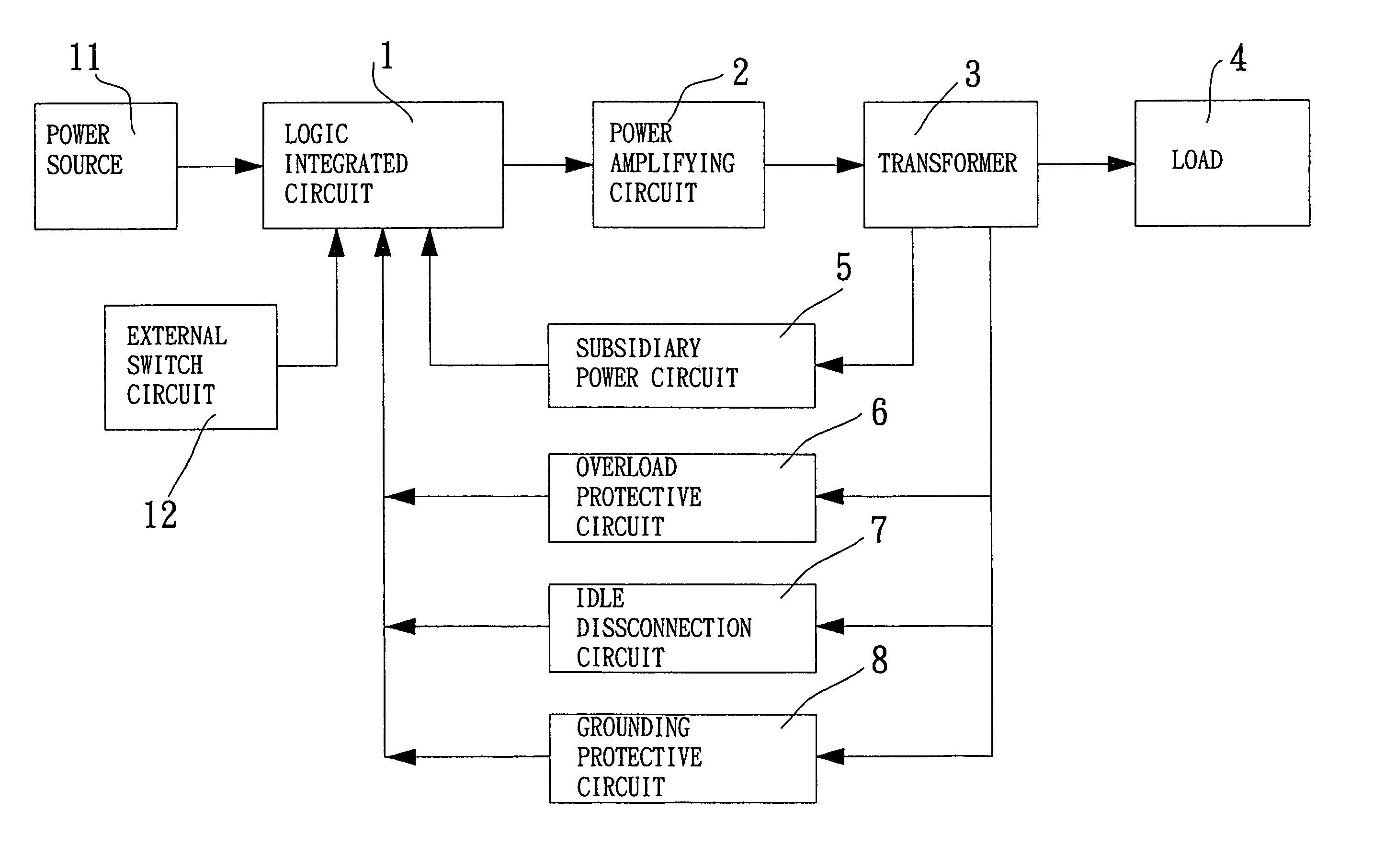
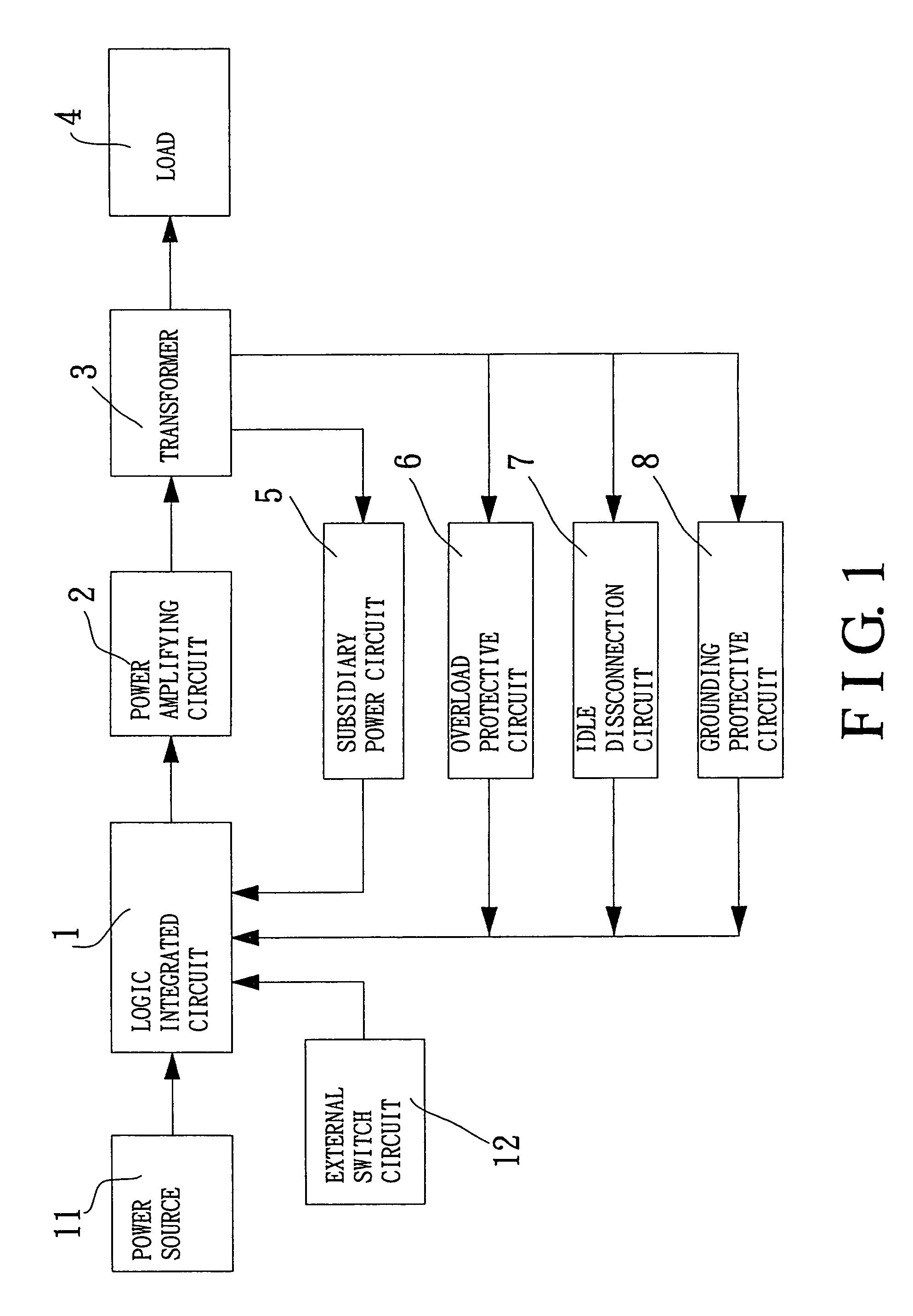
"The present invention provides a high-efficiency controller for gas-filled light producing tubes that overcomes the disadvantages of conventional controllers. The controller includes a logic integrated circuit controlled and oscillated by the pulse width modulation, which drives by voltages or amplifies by push-pull power the inputted electric currents into signals in a form of outputs of high-frequency sine wave (1.414), then amplified and transformed into currents of voltages as needed by the load, i.e. a gas-filled light producing tube, by means of a power amplifier and a transformer. The controller is highly efficient and small in size, and will not become hot when working. The gas-filled tube can meet the efficacies of soft starting, controlling the amplification of power, adjusting the load automatically, examining the overload under abnormal conditions or the disconnection and electric shock of the output terminal. The controller also includes an overload protective circuit, a grounding protective circuit, and an external switch circuit for more convenient use."

Problems solved by technology

However, the above-mentioned conventional ways of starting gas-filled light producing tubes have disadvantages that they are not satisfactorily stable and safe in substantially using because they are prone to cause high-voltage sparks when used, and their lifespan for using on the light producing tubes won't be satisfactorily long that are used with them.

Method used


Image

  • High efficiency controller of a gas-filled light emitting tube
  • High efficiency controller of a gas-filled light emitting tube
  • High efficiency controller of a gas-filled light emitting tube

Examples


Embodiment Construction

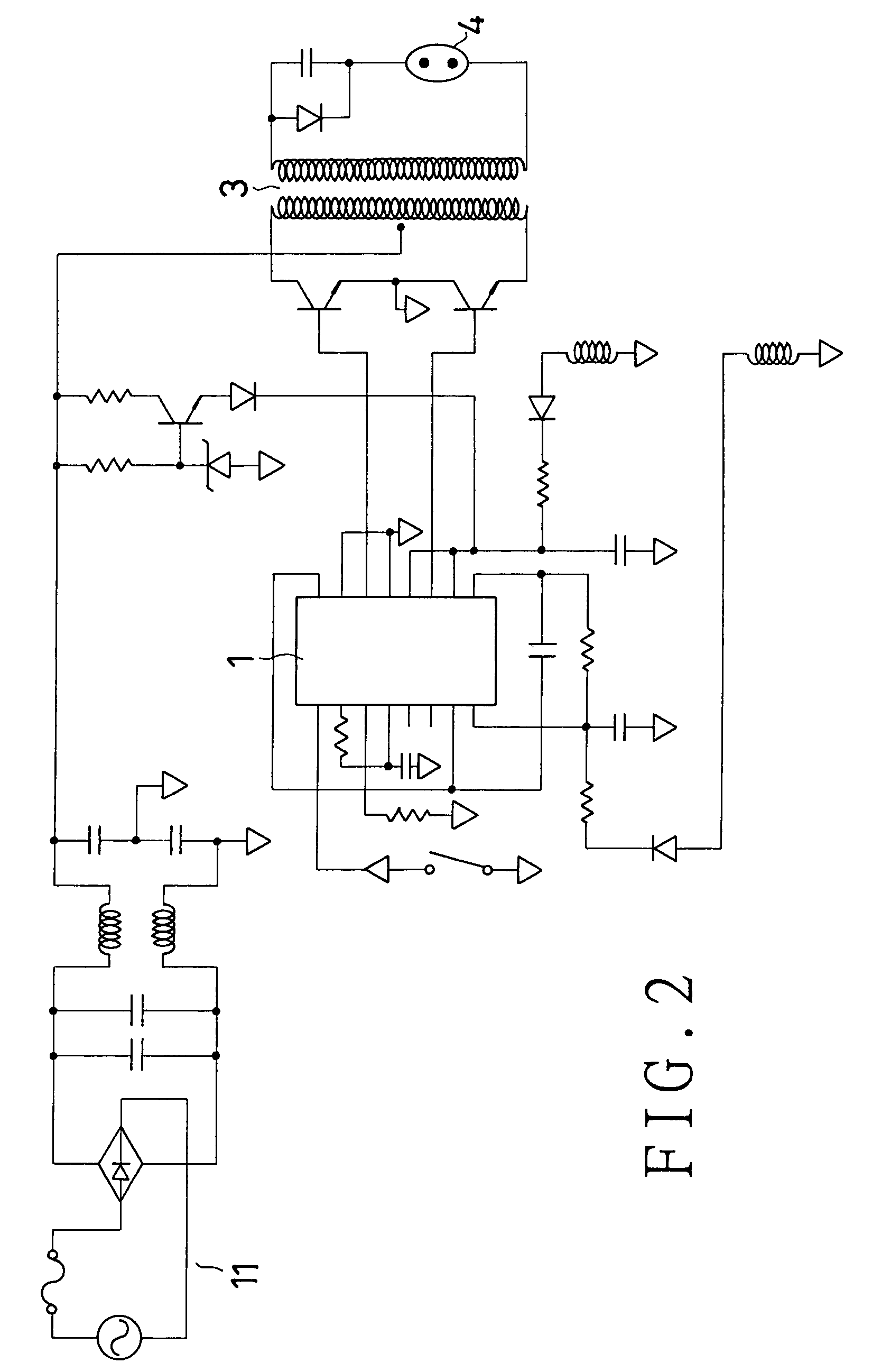
[0015]Referring to FIGS. 1, and 2, a preferred embodiment of a high-efficiency controller of a gas-filled tube in the present invention includes a logic integrated circuit controlled and oscillated by the pulse width modulation 1 (P.W.M.), which is connected to a power source 11 at an input terminal thereof in order to input the direct current power source or the same transformed by the alternative current power source, and is electrically connected to an external switch circuit 12. An output terminal of the logic integrated circuit controlled and oscillated by the pulse width modulation 1 is connected to a power amplifying circuit 2. An output terminal of the power amplifying circuit 2 is electrically connected to a transformer 3, which is connected to a subsidiary power circuit 5, an overload protective circuit 6, an idle disconnection circuit 7, and a grounding protective circuit 8 at an output terminal thereof besides a load 4 such a gas-filled light producing tube. Other end te...


PUM


Abstract

The present invention relates to a high-efficiency controller of a gas-filled light producing tube; the controller can produce signals in a form of outputs of high-frequency sine wave to soft-start a gas-filled light producing tube according to the principle of modulation and oscillation of pulse (P.W.M.) so that the gas-filled tube produces light, and that service light of the gas-filled tube can be lengthened. If abnormal conditions happen, e.g. people's touching the gas-filled tube, and the tube breaking, the controller will make the transformer stop working immediately, preventing sparks from being produced to hurt people, making the gas-filled light producing tube safe to use.12 external switch circuit

Description

BACKGROUND OF THE INVENTION[0001]1. Field of the Invention[0002]The present invention relates to a high-efficiency controller of a gas-filled light producing tube, which can help a gas-filled light producing tube have long lifespan for using, and which can form an broken circuit automatically in case human body contacts the gas-filled tube or the gas-filled tube breaks; thus, it can present the best efficacy of using safely.[0003]2. Brief Description of the Prior Art[0004]Various artificial light sources play important roles in human daily living, not only providing illumination to people in the dark but also being used a lot for making different styles of advisements. Of various artificial light sources, various Gas-filled light producing tubes, provided with the interior gas-filled, are most common.[0005]Conventional starters for gas-filled light producing tubes consist of steel plates made of silicon, which are provided for changing low-frequency alternative electric currents (50...

Claims


Application Information

Patent Timeline
Patent Type & Authority Patents(United States)
IPC IPC(8): H05B37/02G05F1/00H02M7/5381H05B41/292H05B41/392
CPCH02M7/5381H05B41/3928H05B41/2925H02M1/32Y10S315/07
Inventor CHEN, OWEN
Owner CHEN OWEN
Learn More