Sample and hold circuits and methods with offset error correction and systems using the same

a technology of offset error correction and circuit, applied in the field of mixed signal processing, can solve the problems of severe linearity requirements nonlinear sampling current, and increased current requirements, so as to reduce the loading on the input signal source, increase the input impedance, and increase the oversampling rate

Active Publication Date: 2006-08-08
CIRRUS LOGIC INC
View PDF5 Cites 39 Cited by
  • Summary
  • Abstract
  • Description
  • Claims
  • Application Information

AI Technical Summary

Benefits of technology

[0007]The principles of the present invention realize substantial advantages over the prior art, particularly when embodied in a sample and hold stages and similar circuits operating at relatively high oversampling rates. These principles allow for a substantial reduction of the loading on the input signal source by increasing the input impedance of the embodying circuit or system. Additionally, linearity of the circuit system is improved as a result of a substantial reduction in non-linear charge drawn from a signal source.

Problems solved by technology

In high sampling rate applications, such as delta sigma ADCs, this current requirement becomes even more severe due to the relatively small amount of time available during each sampling event to charge the sampling capacitor.
Furthermore, the sampling current is often nonlinear due to charge injection and nonlinear input impedances caused by the switching circuitry controlling the charging of the sampling capacitor, which in turn mandates severe linearity requirements on the input signal source.

Method used


Image

  • Sample and hold circuits and methods with offset error correction and systems using the same
  • Sample and hold circuits and methods with offset error correction and systems using the same
  • Sample and hold circuits and methods with offset error correction and systems using the same

Examples


Embodiment Construction

[0014]The principles of the present invention and their advantages are best understood by referring to the illustrated embodiment depicted in FIGS. 1–5 of the drawings, in which like numbers designate like parts.

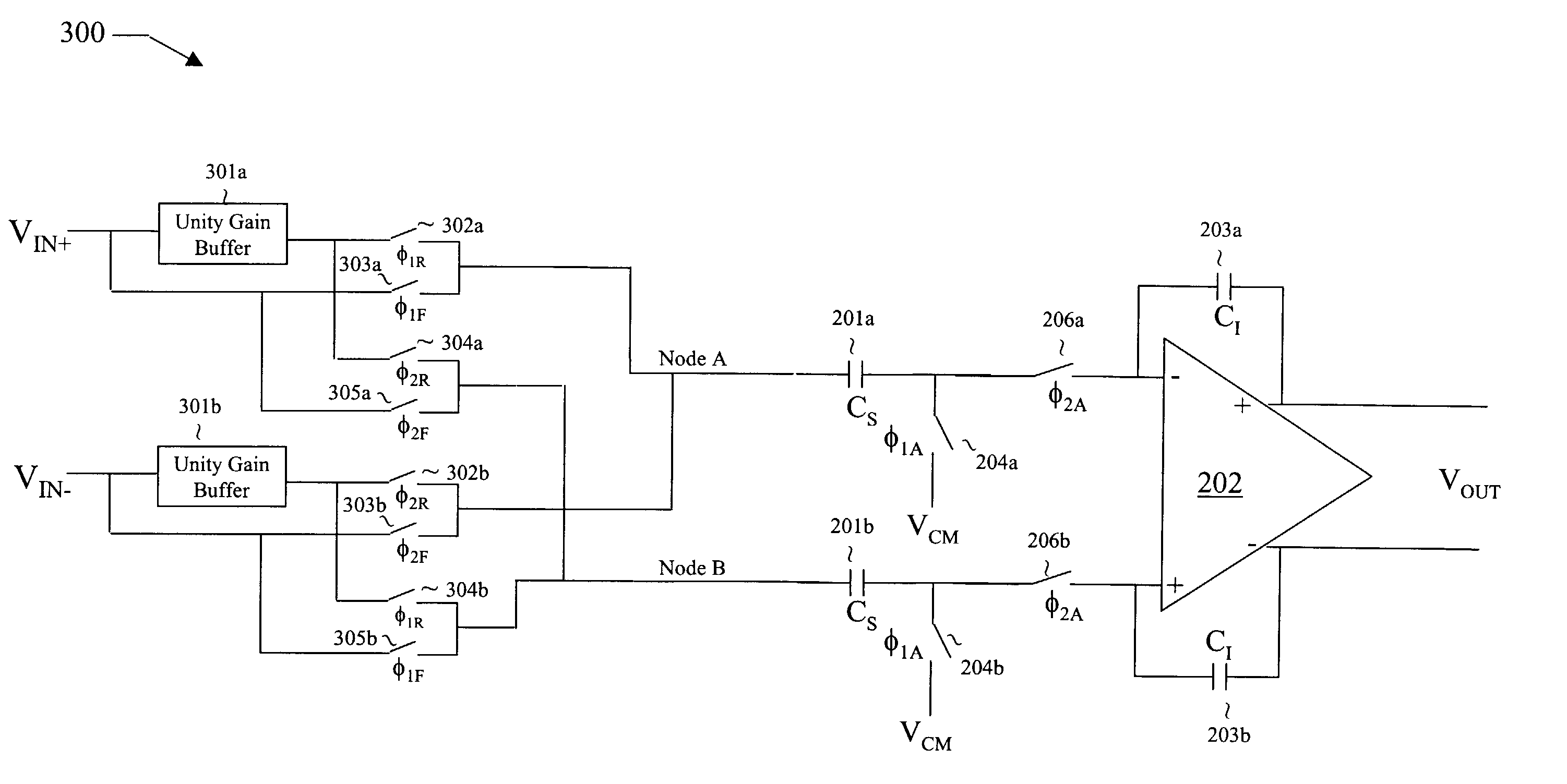
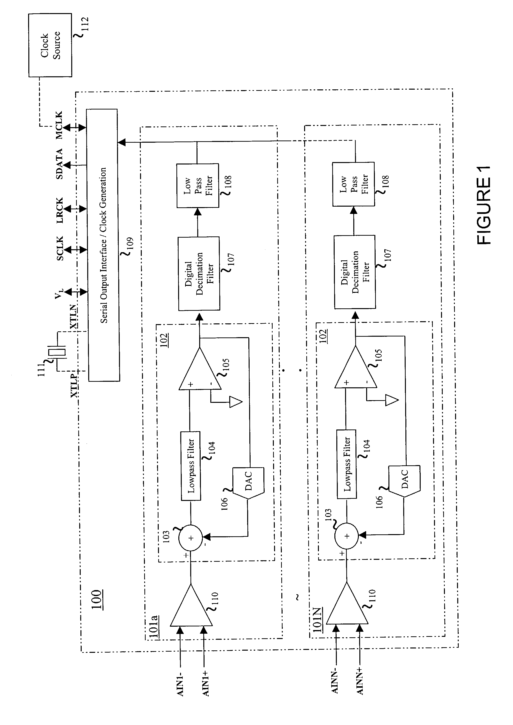
[0015]FIG. 1 is a high-level block diagram of a single-chip audio analog-to-digital converter (ADC) 100 suitable for practicing the principles of the present invention. For illustrative purposes, ADC 100 is a delta-sigma ADC, although the present inventive principles are applicable to other types of ADCs, as well as digital-to-analog converter (DACs) and Codecs.

[0016]ADC 100 includes N conversion paths 101a, b, . . . N, of which two paths 101a and 101N are shown for reference, for converting N channels of differential analog audio data respectively received at analog differential inputs AINN+ / −, where N is an integer of one (1) or greater. The analog inputs AINN+ / − for each channel are passed through an input sample and hold 110 and then a delta-sigma modulator 102 which per...


PUM

PropertyMeasurementUnit
input offset voltageaaaaaaaaaa
output voltageaaaaaaaaaa
offset voltageaaaaaaaaaa

Abstract

A sample and hold circuit including a sampling capacitor for storing a sample of an input signal, an output stage for outputting the sample stored on the sampling capacitor; and input circuitry for sampling the input signal and storing the sample on the sampling capacitor. The input circuitry includes an autozeroing input buffer which selectively samples the input signal during a first operating phase and holds a sample of the input signal during a second operating phase. The autozeroing input buffer cancels any offset error. The input circuitry also includes switching circuitry for selectively coupling the sampling capacitor with an input of the sample and hold circuitry during the second operating phase and to an output of the autozeroing input buffer during the first operating phase.

Description

FIELD OF INVENTION[0001]The present invention relates in general to mixed signal processing and in particular to sample and hold circuits and methods with offset error correction and systems using the same.BACKGROUND OF INVENTION[0002]Data acquisition systems, such as analog to digital converters (ADCs), normally include a front-end sample and hold stage for capturing an input signal. Typically, this sample and hold stage is implemented with a switched-capacitor circuit in which a sampling capacitor is switched between sampling and integrating modes. Generally, during the sampling mode, the input signal is sampled onto the sampling capacitor and during the integration phase, the charge on the sampling capacitor is transferred to an integrating capacitor.[0003]In order to maintain a high dynamic range, the sampling capacitor in switched-capacitor circuits, such as sample and hold stages, must be large to minimize[0004]KTCnoise. Therefore, high dynamic range sample and hold circuits r...

Claims


Application Information

Patent Timeline
Patent Type & Authority Patents(United States)
IPC IPC(8): G11C27/02G11B20/10
CPCG11C27/024
Inventor PRASAD, AMMISETTI V.THOMPSON, KARLMELANSON, JOHN LAURENCESOMAYAJULA, SHYAM
Owner CIRRUS LOGIC INC
Why Eureka
Try Eureka