RFID tag and method for processing RFID data

a technology of rfid tags and data, applied in the field of rfid systems, can solve the problems of significant degraded communication performance, tags cannot effectively access the interrogator (reader/writer), and achieve the effect of stable system operation and simple construction

Inactive Publication Date: 2006-08-08
ORMON CORP
View PDF5 Cites 123 Cited by
  • Summary
  • Abstract
  • Description
  • Claims
  • Application Information

AI Technical Summary

Benefits of technology

[0009]An exemplary RFID tag configuration, which makes effective use of a collision prevention relational function (called “anti-collision

Problems solved by technology

When RFID tags 1 are affixed to items such as books, envelopes, casino chips, and so on, problems occur when tags 1 overlap one another.
In such cases, communication performance is degraded significantly and the tags cannot effectively access to the interrogator (reader/writer) 2.
In

Method used


Image

  • RFID tag and method for processing RFID data
  • RFID tag and method for processing RFID data
  • RFID tag and method for processing RFID data

Examples


Embodiment Construction

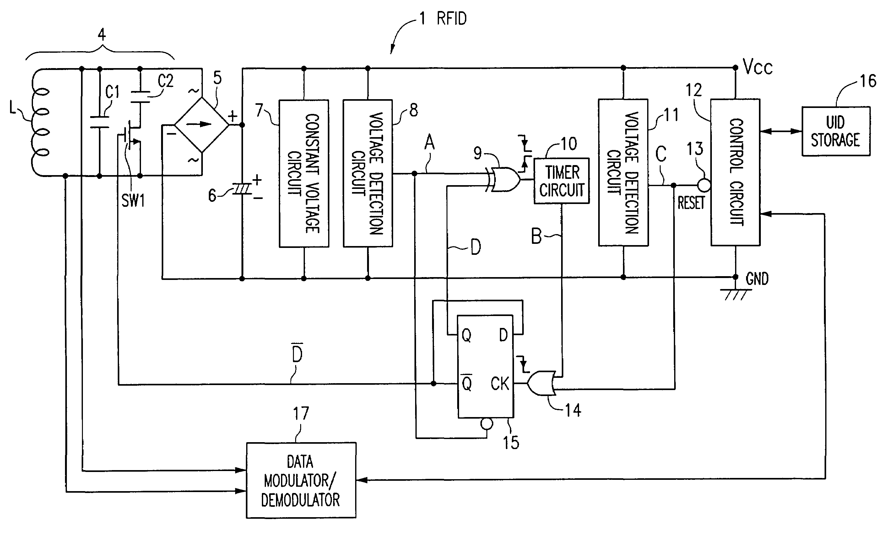
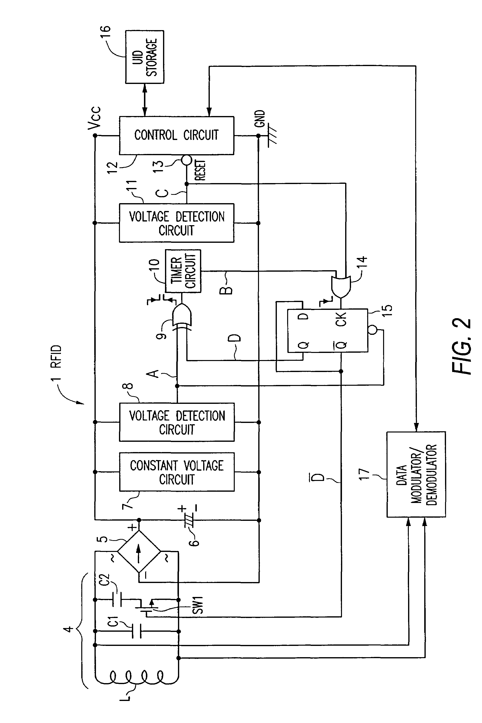
[0029]FIG. 2 illustrates an RFID tag 1, where voltage detection circuits 8, 11 are referred to as a voltage monitoring portion, latch circuit 15 is referred to as a resonance capacitive switching command portion, and a control circuit 12, UID storage circuit 16, and a data modulator / demodulator 17 are referred to as anti-collision information output circuit portion. Coil L, resonance capacitor C1, and an adjustment capacitor C2 constitute a parallel resonance circuit 4. Switching circuit SW1 is preferably formed on a semiconductor substrate, such as a CMOS-FET, is set to be on in an initial state.

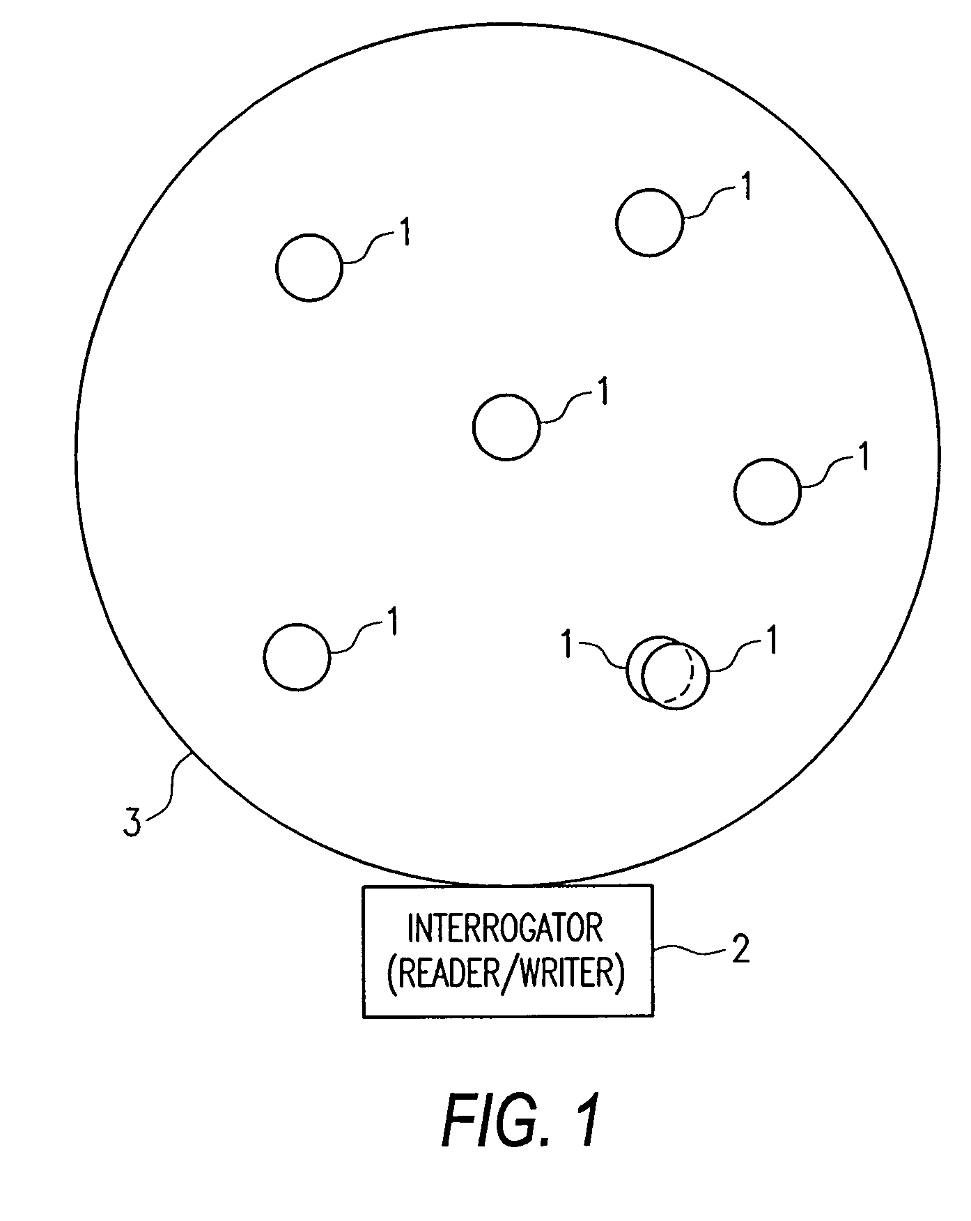
[0030]The adjustment capacitor C2 and the resonance capacitor C1 of FIG. 2 are connected parallel to each other and are contained in the resonance circuit 4. The resonance circuit 4 resonates when it enters into a high-frequency field, located in detection area 3, generated by an antenna of an interrogator (reader / writer) 2, and its resonant output is applied to a rectification circuit 5. I...


PUM


Abstract

A collision prevention relational function is disclosed for RFID tags, which increases stability during system operations. The RFID tag includes a parallel resonance circuit having a coil, a resonance capacitor, an adjustment capacitor, a switching circuit, a rectification circuit, a smoothing capacitor, a constant-voltage circuit, a voltage detection circuit, an exclusive OR circuit, a timer circuit, a voltage detection circuit, a control circuit, an OR circuit, a latch circuit, an UID storage device, and a data modulator/demodulator. When a predetermined power supply voltage/operating voltage is obtained, an anti-collision algorithm identifies and adjusts RFID tags that experienced collision.

Description

[0001]The present invention relates to RFID tags and an RFID interrogator making use of the same.BACKGROUND OF THE INVENTION[0002]FIG. 1 illustrates a typical RFID system comprising of a plurality of RFID tags 1 affixed to a detection area 3, associated with an interrogator (reader / writer). The detection area 3 is typically configured to operate within a predetermined field, where the field reads tags 1 present within a detection area 3.[0003]When RFID tags 1 are affixed to items such as books, envelopes, casino chips, and so on, problems occur when tags 1 overlap one another. In such cases, communication performance is degraded significantly and the tags cannot effectively access to the interrogator (reader / writer) 2. Overlaps typically occur when RFID tags 1 stack on one another (denoted by the dotted line in FIG. 1), or when spacing between various tags 1 is set to be very small.[0004]In such cases, the inductance of the resonance coil (Ls) of certain tags 1 interconnect with eac...

Claims


Application Information

Patent Timeline
IPC IPC(8): G08B13/14G06K7/00G06K17/00G06K19/07H04B1/59H04B5/02
CPCG06K7/0008G06K19/0726G06K19/0723G06K7/10029
Inventor FUKUOKA, SHINICHIRO
Owner ORMON CORP
Why Eureka
Try Eureka