Method of selecting a light redirecting film

Inactive Publication Date: 2006-08-15
RAMBUS DELAWARE
View PDF22 Cites 101 Cited by
  • Summary
  • Abstract
  • Description
  • Claims
  • Application Information

AI Technical Summary

Benefits of technology

[0009]The present invention relates to light redirecting films and light redirecting film systems that redistribute more of the light emitted by a backlight or other light source toward a direction more normal to the plane of the

Problems solved by technology

A matte finish produces a softer image but is not as bright due to the additional scattering and resultant light loss caused by the matte or diffuse surface.
However, such a film produces a much lower brightness than two film layers each with a single groove configura

Method used


Image

  • Method of selecting a light redirecting film
  • Method of selecting a light redirecting film
  • Method of selecting a light redirecting film

Examples


Embodiment Construction

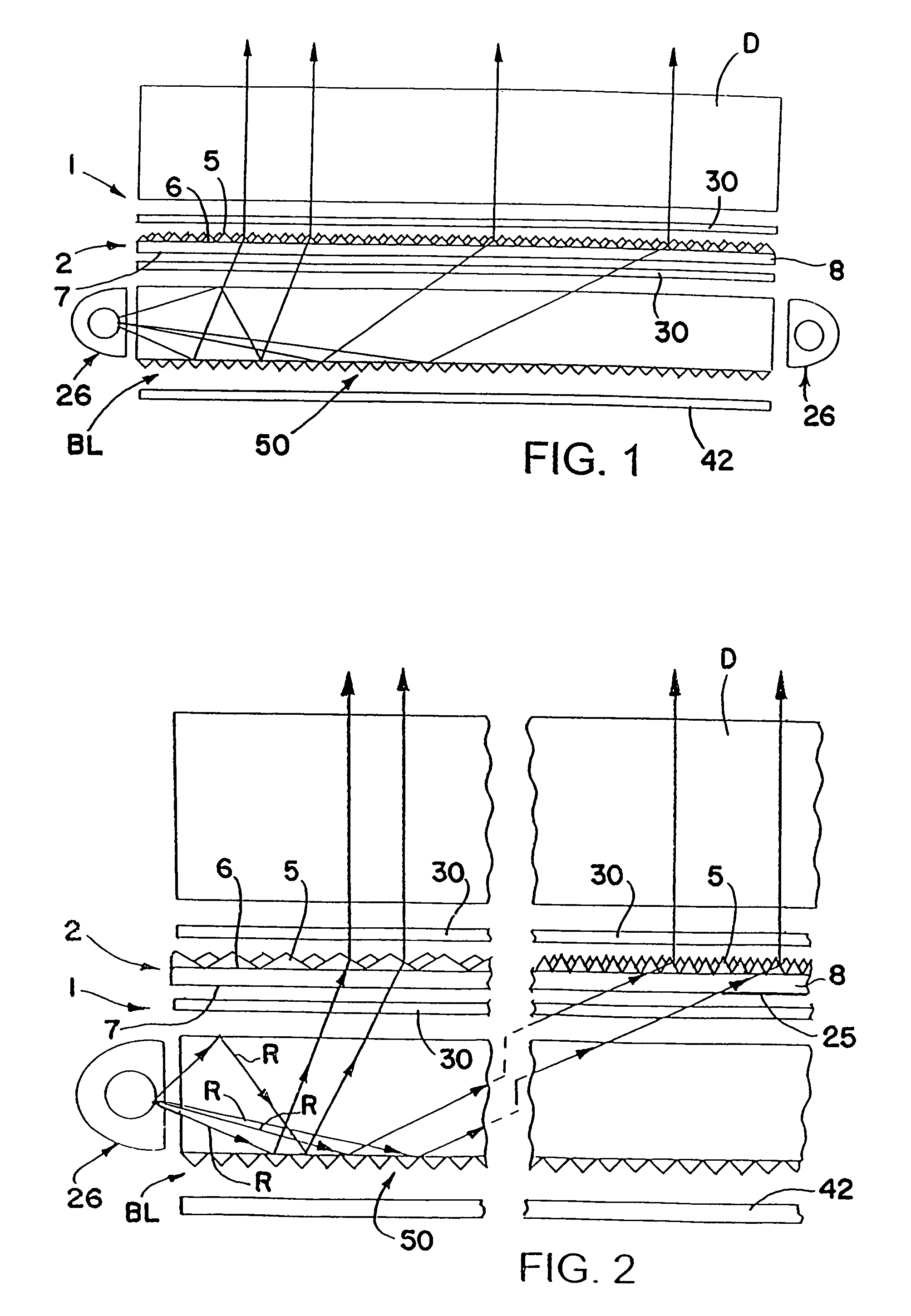
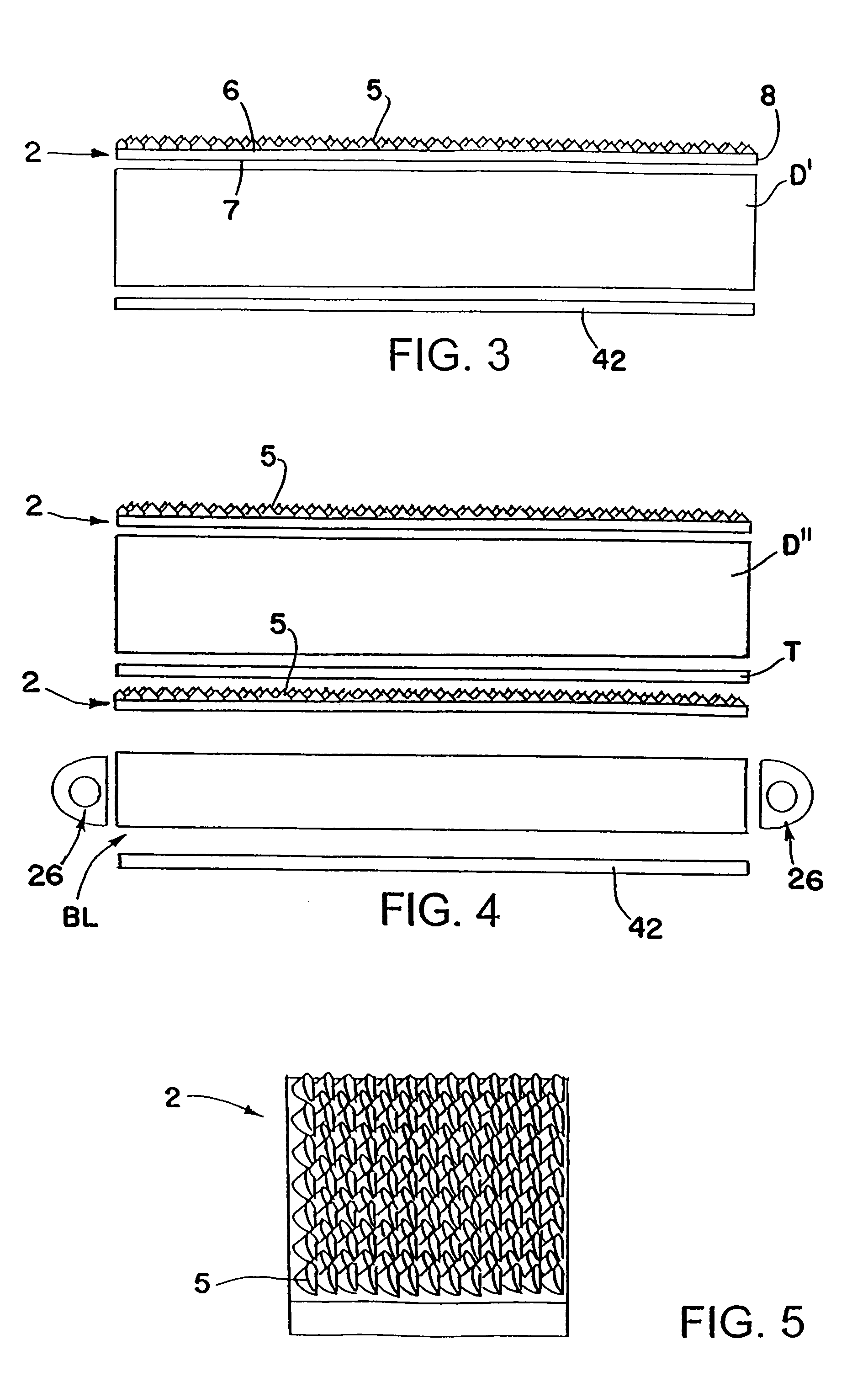
[0039]FIGS. 1 and 2 schematically show one form of light redirecting film system 1 in accordance with this invention including a light redirecting film 2 that redistributes more of the light emitted by a backlight BL or other light source toward a direction more normal to the surface of the film. Film 2 may be used to redistribute light within a desired viewing angle from almost any light source for lighting, for example, a display such as a liquid crystal display, used in laptop computers, word processors, avionic displays, cell phones, PDAs and the like, to make the displays brighter. The liquid crystal display can be any type including a transmissive liquid crystal display D as schematically shown in FIGS. 1 and 2, a reflective liquid crystal display DI as schematically shown in FIG. 3 and a transflective liquid crystal display DII as schematically shown in FIG. 4.

[0040]The reflective liquid crystal display D′ shown in FIG. 3 includes a back reflector 42 adjacent the back side fo...


PUM


Abstract

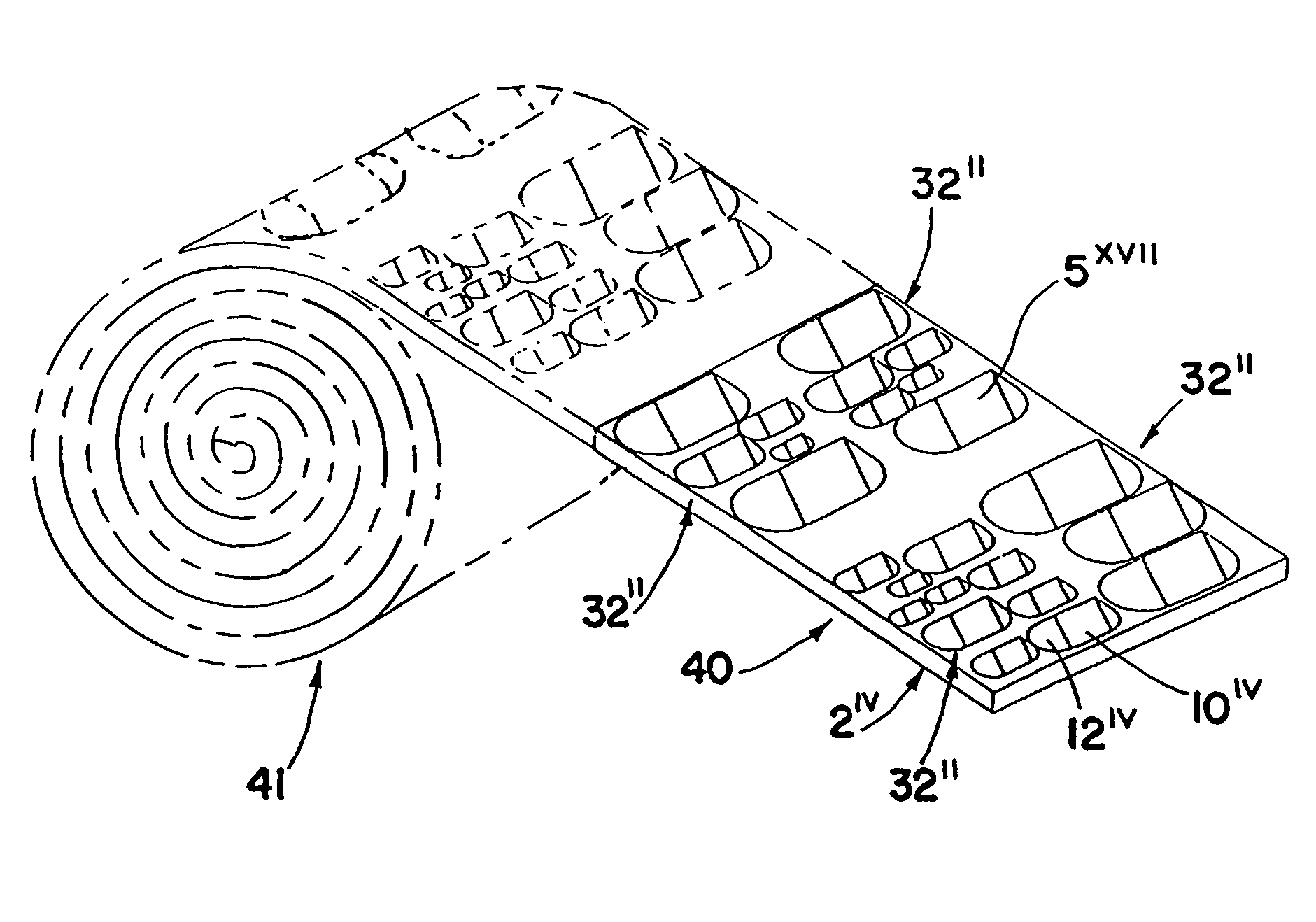
The method of selecting a light redirecting film or optical panel includes the steps of providing a length of film or substrate having a pattern of optical elements that varies, then selecting an area of the film or substrate that has a pattern of the optical elements that best suits a particular application, and removing the selected area from the film or substrate to provide the light redirecting film or optical panel. The pattern may be a repeating pattern that varies at different locations on the film or substrate and may comprise a roll of the film or substrate from which the selected area(s) is removed.

Description

CROSS-REFERENCE TO RELATED APPLICATIONS[0001]This application is a division of U.S. patent application Ser. No. 09 / 909,318, filed Jul. 19, 2001, now U.S. Pat. No. 6,752,202, which is a continuation-in-part of U.S. patent application Ser. No. 09 / 256,275, filed Feb. 23, 1999, now U.S. Pat. No. 6,712,481, the entire disclosures of which are incorporated herein by reference.FIELD OF THE INVENTION[0002]This invention relates to light redirecting films and film systems for redirecting light from a light source toward a direction normal to the plane of the films.BACKGROUND OF THE INVENTION[0003]Light redirecting films are thin transparent or translucent optical films or substrates that redistribute the light passing through the films such that the distribution of the light exiting the films is directed more normal to the surface of the films. Heretofore, light redirecting films were provided with prismatic grooves, lenticular grooves, or pyramids on the light exit surface of the films whic...

Claims


Application Information

Patent Timeline
IPC IPC(8): F21V7/22G02B6/00A61B19/00F21V5/00F21V8/00F21Y101/02F21Y103/00G02F1/13357
CPCF21V11/00F21V5/00G02B6/0018G02B6/002G02B6/0021G02B6/0036G02B6/0038G02B6/0053G02B6/0061G02B6/0065G02B6/0068A61M21/02A61B2019/521A61M2021/0044A61N5/0621A61N2005/063A61N2005/0652G02B6/0028G02B6/0031G02B6/0043G02B6/006H01H2219/062H01H2221/07A61B2090/309F21V5/10
Inventor PARKER, JEFFERY R.MCCOLLUM, TIMOTHY A.EZELL, ROBERT M.
Owner RAMBUS DELAWARE
Why Eureka
Try Eureka