Liquid-continuous column distillation

a liquid-continuous column and column technology, applied in the direction of oxygen compound purification/separation, sustainable manufacturing/processing, and separation processes, can solve the problems of no steady-state operation and the reboiler will run dry, and achieve the effect of steady-state operation

Inactive Publication Date: 2006-08-15
CHEM RES & LICENSING CO
View PDF12 Cites 5 Cited by
  • Summary
  • Abstract
  • Description
  • Claims
  • Application Information

AI Technical Summary

Problems solved by technology

Above this point, the reboiler will run dry and no steady state operation can be maintained.

Method used


Image

  • Liquid-continuous column distillation
  • Liquid-continuous column distillation
  • Liquid-continuous column distillation

Examples


example

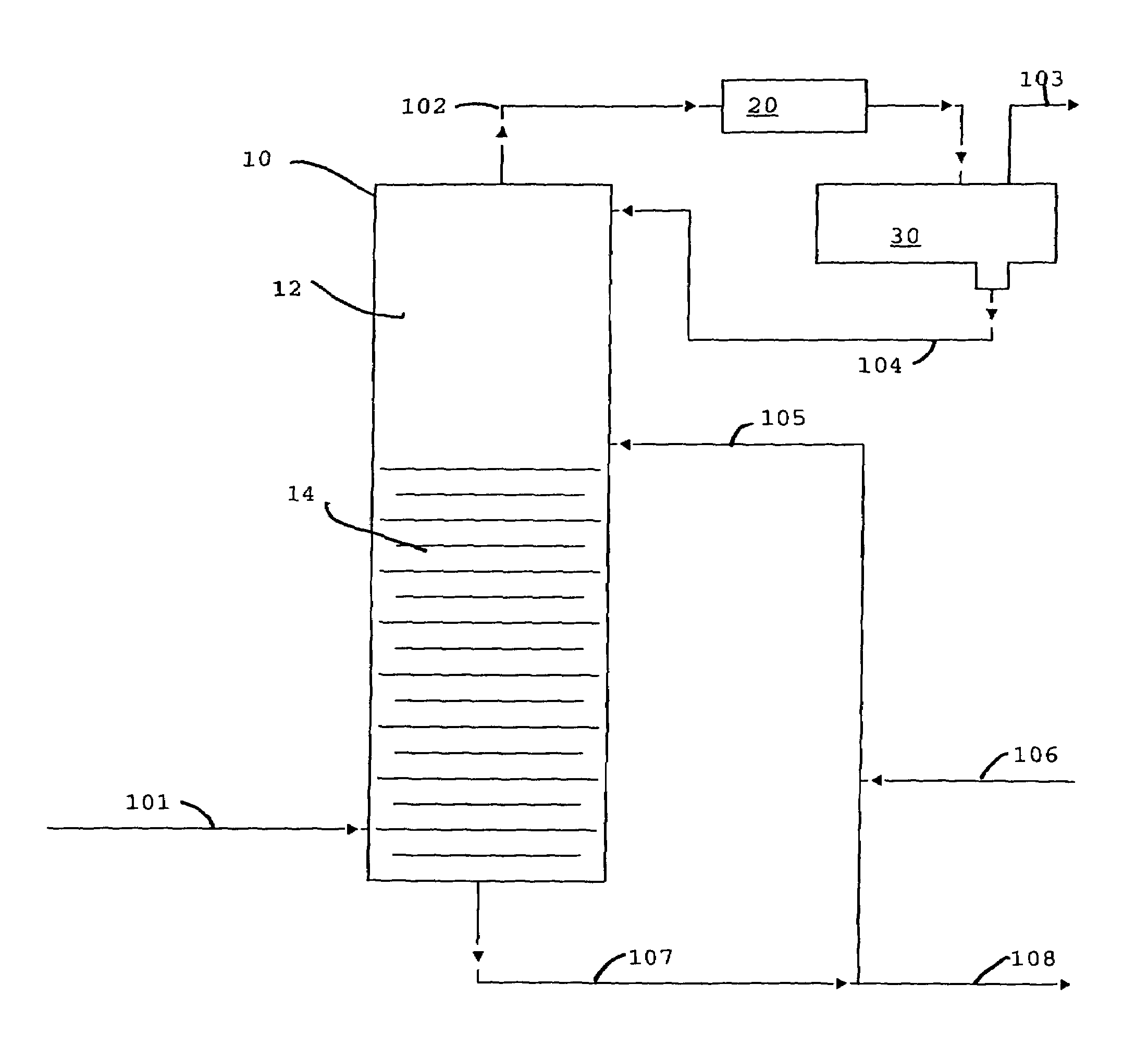
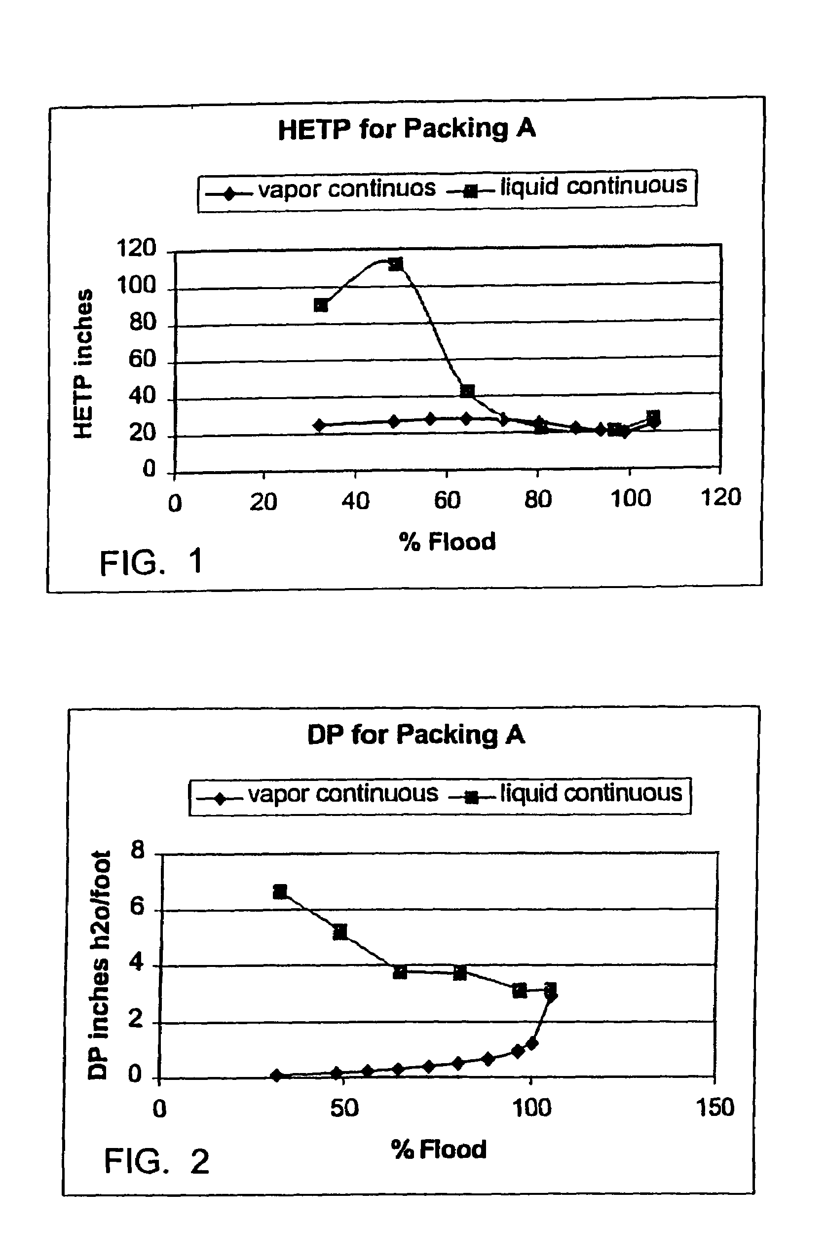
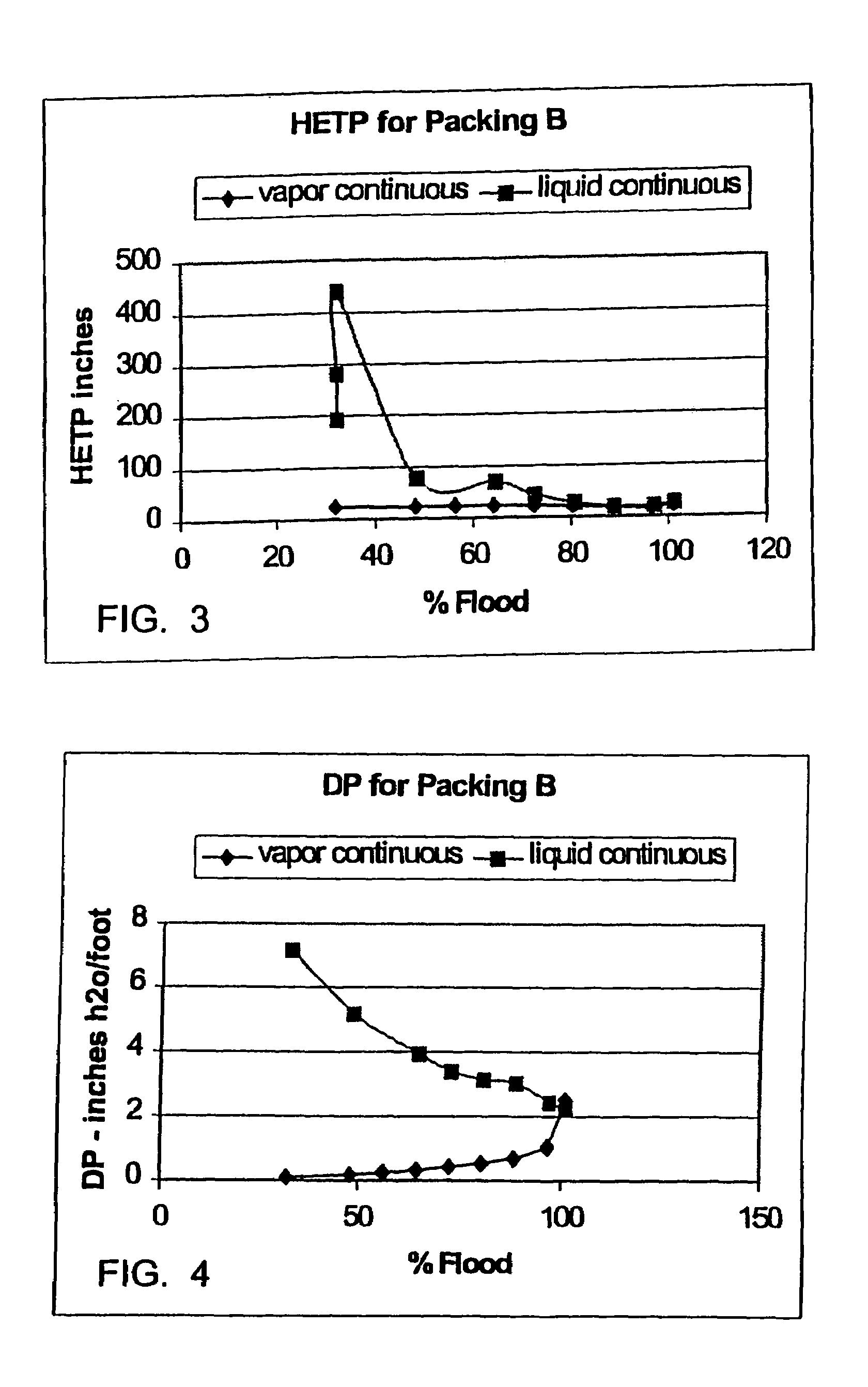
[0024]Testing was conducted using a system of n-heptane and cyclohexane at 24 PSIA in a 16.8 inch diameter tower. The Fig.s are graphs of data from various packings. The packings are those described in U.S. Pat. No. 5,730,840 with different particulate loadings. The column packing or other internals (including trays or heat exchanger bundles) will affect the jet flood point but will not significantly alter the performance improvements disclosed here that result from operating at a high vapor rate expressed as a % of jet flood.

[0025]As can be seen in each case in FIGS. 1, 3 and 5, the vapor—liquid mass transfer efficiency, as indexed by HETP, improved as the vapor rate increased above about 50% of jet flood. Above about 70% of jet flood the performance was practically the same whether in bubble column mode (liquid continuous) or distillation tower mode (vapor continuous).

[0026]As the liquid level was raised from the reboiler to the top of the packing there was a seamless, uneventful ...


PUM

PropertyMeasurementUnit
temperatureaaaaaaaaaa
molar ratioaaaaaaaaaa

Abstract

Bubble columns fractionate with vapor-liquid mass transfer efficiencies approaching that of distillation towers when vapor velocities in excess of 50% of jet flood are used. If the vapor velocities are pushed above about 70% of jet flood then the distillation performance of a given column packing becomes similar for both liquid continuous operation (bubble column mode) and vapor continuous operation (ordinary distillation tower mode).

Description

[0001]This is a division of application Ser. No. 10 / 357,123 filed on Feb. 3, 2003 now abandoned which claims the benefit of U.S. Provisional Application No. 60 / 359,209, filed Feb. 22, 2002.BACKGROUND OF THE INVENTION[0002]1. Field of the Invention[0003]The present invention relates to the operation of liquid-continuous distillation columns, in particular bubble columns.[0004]2. Related Information[0005]In its broadest sense a bubble column may be a column of liquid with a stream of gas bubbles passing upward through the liquid. Thus, these systems (excluding the column) are comprised of at least two components, i.e., the liquid and the gas. In these systems, unless it is an esthetic display item such as a lava lamp, there is an interaction between the liquid and the gas. For example, in a fish tank, air bubbling up through a column of water is partially absorbed into the water. In other systems, for example, an impure gaseous mixture may be passed through a liquid wash to remove the...

Claims


Application Information

Patent Timeline
Patent Type & Authority Patents(United States)
IPC IPC(8): C07C27/00B01D3/00B01D3/14C07C29/151
CPCB01D3/009B01D3/14C07C7/04C07C29/1512C07C31/04Y02P20/10B01D3/34C07C27/28
Inventor SMITH, JR., LAWRENCE A.LOESCHER, MITCHELL E.
Owner CHEM RES & LICENSING CO
Why Eureka
Try Eureka