Miniature 2-dimensional encoder readhead using fiber optic receiver channels

a fiber optic receiver and encoder technology, applied in the field of displacement sensing optical encoders, can solve the problems of long cables without significant signal loss or interference, photodetectors, and long cables, and achieve the effects of high speed, high accuracy, and ultra-compactness

Active Publication Date: 2006-08-15
MITUTOYO CORP
View PDF10 Cites 9 Cited by
  • Summary
  • Abstract
  • Description
  • Claims
  • Application Information

AI Technical Summary

Benefits of technology

[0022]Hence, the invention overcomes the disadvantages of prior art 2D optical displacement sensing devices and provides new application possibilitie

Problems solved by technology

In addition to the fact that the previously disclosed '283 patent is directed only to a single dimension measurement system, as previously outlined, electronic readhead receivers (photodetectors) such as disclosed in the '283 patent suffer limitations in converting the high frequency detector signals associated with high speed scale motion and transmitting those signals over long cables without significant signal loss or interference.
In addition, electronic photodetectors and the associated circuit connections contribute to readheads that

Method used


Image

  • Miniature 2-dimensional encoder readhead using fiber optic receiver channels
  • Miniature 2-dimensional encoder readhead using fiber optic receiver channels
  • Miniature 2-dimensional encoder readhead using fiber optic receiver channels

Examples


Embodiment Construction

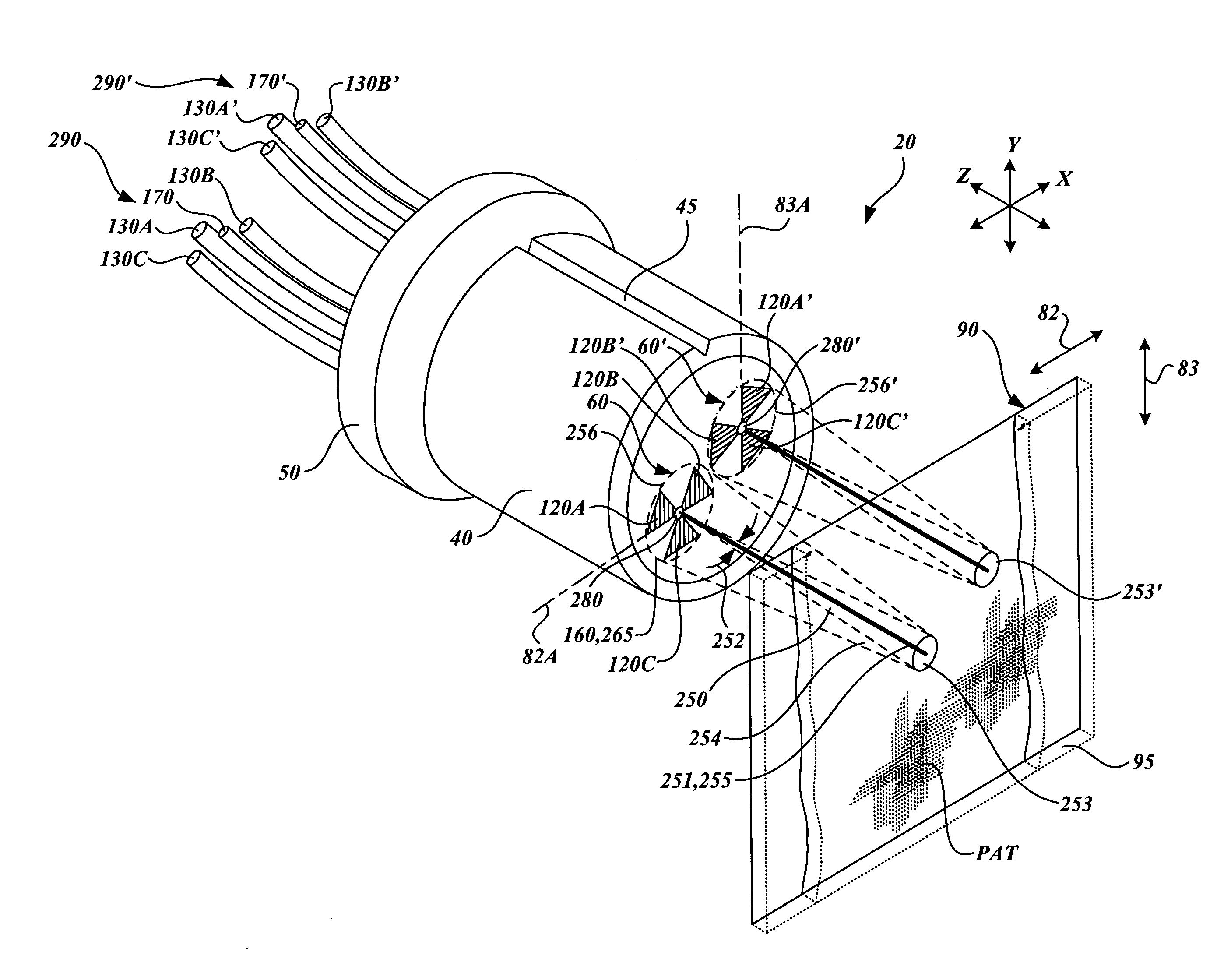
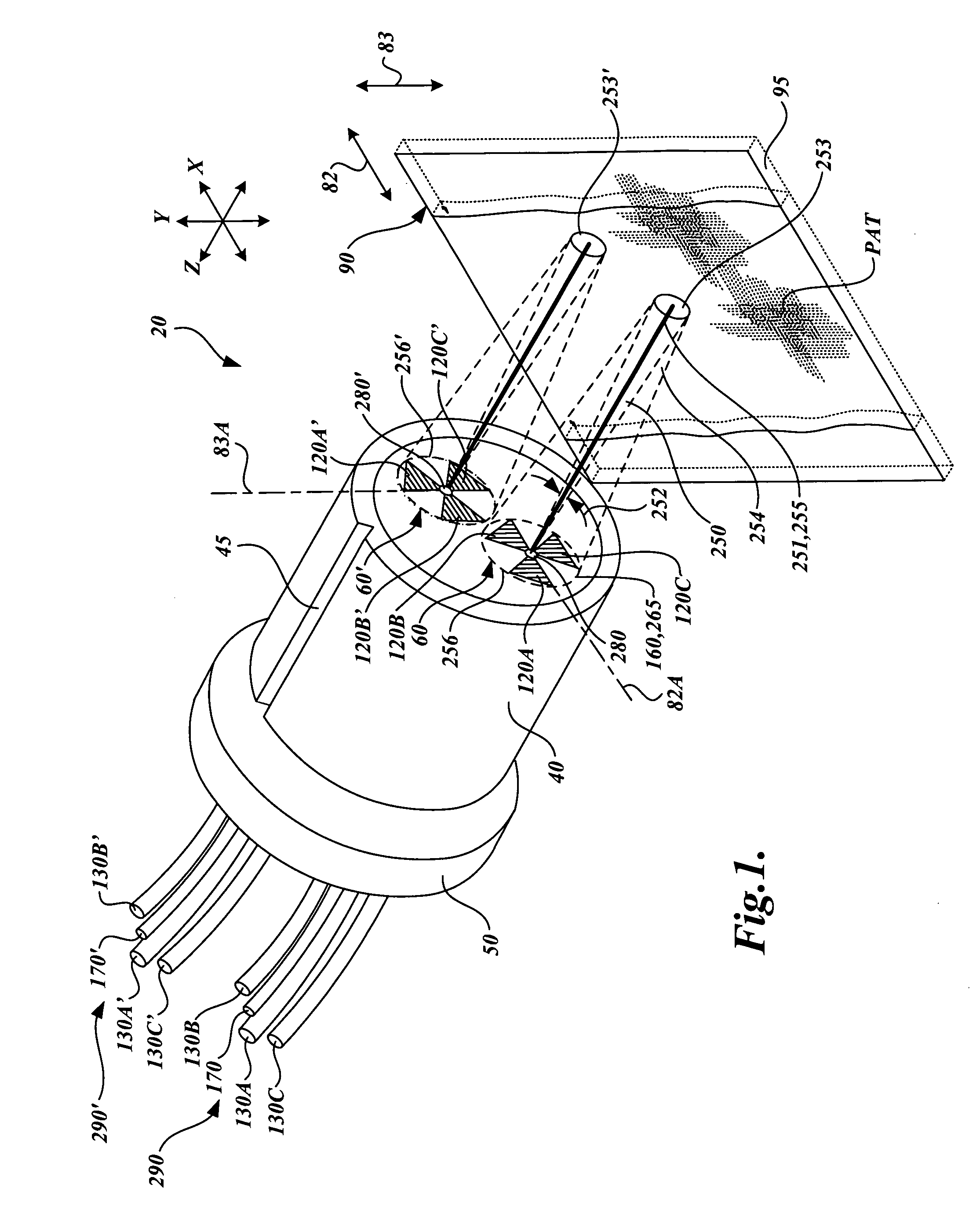
[0033]FIG. 1 shows a first generic embodiment of a 2D fiber optic readhead arrangement 20 according to this invention. As shown in FIG. 1, the 2D fiber optic readhead arrangement 20 includes a ferrule 40 which has an alignment groove 45 and an alignment collar 50, and which encases two readhead portions 60 and 60′. The readhead portions 60 and 60′ may be formed in accordance with the teachings of U.S. patent application Ser. No. 10 / 298,312, entitled “High Accuracy Miniature Grating Encoder Readhead Using Fiber Optic Receiver Channels,” filed Nov. 15, 2002, which is commonly assigned and hereby incorporated by reference in its entirety. As will be described in more detail below, each of the readhead portions 60 and 60′ corresponds to a measurement axis 82 and 83, respectively, which are referenced to a scale 90 including a pattern PAT, which is formed on a substrate 95. It should be understood that the scale 90 can extend to any desired dimensions along the direction of the measuring...


PUM


Abstract

A 2D fiber optic encoder readhead having multiple readhead portions for sensing the two-dimensional displacement of a scale grating is disclosed. The detector channels of the readhead portions are fiber optic detector channels having respective phase grating masks. At least two of the phase grating masks have different orientations so as to facilitate the detection of displacement in at least two different directions. The 2D fiber optic encoder readhead portions are configured to detect the displacement of a self-image pattern that results from a corresponding pattern on the scale grating. The self-image pattern allows for the detection of displacement in the at least two different directions. In various exemplary embodiments, the fiber optic readhead portions are constructed according to various design relationships that insure a robust signal-to-noise ratio. Accordingly, high levels of displacement signal interpolation may be achieved. The 2D fiber optic encoder readhead portions may be assembled in a particularly accurate and economical manner and may be provided in a package with dimensions on the order of 1–2 millimeters, resulting in a very small overall readhead dimension that is dependent on the number of readhead portions that are incorporated.

Description

FIELD OF THE INVENTION[0001]This invention relates generally to displacement sensing optical encoders, and more particularly to an optical encoder utilizing optical fibers as receiver elements to provide an ultra-compact 2-dimensional position measuring system.BACKGROUND OF THE INVENTION[0002]Various movement or position encoders for sensing 1-dimensional (1D) linear, rotary or angular movement are currently available. These encoders are generally based on either optical systems, magnetic scales, inductive transducers, or capacitive transducers. Certain of these encoders are designed for making relative measurements. In such relative displacement or position encoders, measurements are typically made by sensing the relative change in position of the scales with respect to a reference position, which requires a sensing of the change in the scale pattern so that repetitions of the pattern can be counted. This type of position measurement may be referred to as incremental displacement m...

Claims


Application Information

Patent Timeline
IPC IPC(8): G01B9/02G01D5/30G01B11/00G01D5/347G02B6/293G02B6/34
CPCG01D5/34723G01D5/268
Inventor TOBIASON, JOSEPH D.
Owner MITUTOYO CORP
Why Eureka
Try Eureka