
Multilevel copper interconnects with low-k dielectrics and air gaps

a multi-level copper and air gap technology, applied in the field of integrated circuits, can solve the problems of complex additional processing steps and failure to provide an added benefi

Inactive Publication Date: 2006-08-15
ROUND ROCK RES LLC
View PDF237 Cites 63 Cited by
  • Summary
  • Abstract
  • Description
  • Claims
  • Application Information

AI Technical Summary

Benefits of technology

"The present invention provides a solution for addressing issues associated with integrated circuit size and performance, via and metal line formation, and other problems. The invention provides a method for forming multilevel wiring interconnects in an integrated circuit assembly using selective electroless copper metallization. A low dielectric constant material is deposited between the metal lines and the substrate using a directional process, which includes maintaining air gaps in the low dielectric constant material. The invention also provides various methods for depositing the low dielectric constant material, such as using an organic silica film, a microwave plasma-assisted supersonic jet deposition process, a quasi hydrogen-free chemical vapor deposition process, a polymer-like organic thin film, or a para-xylene precursor. The technical effects of the invention include reducing inter-level and intra-level line-to-line capacitance, improving signal transmission speed, and enhancing overall performance of the integrated circuit assembly."

Problems solved by technology

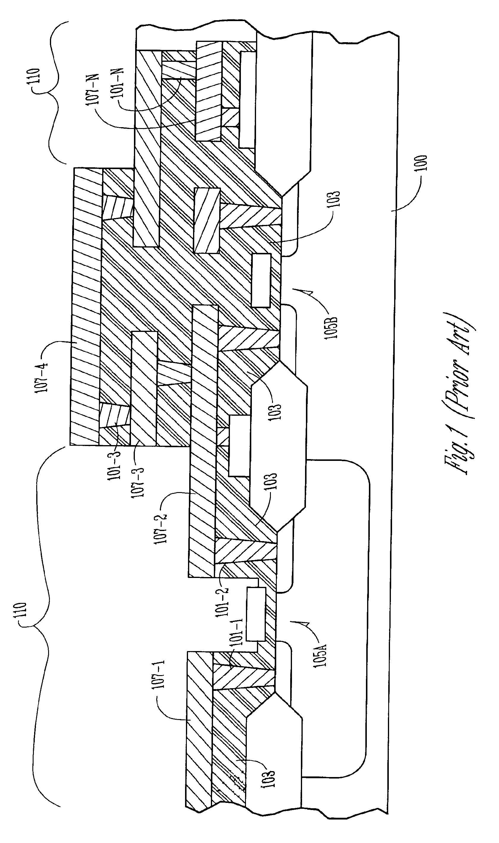
As the integrated circuit (IC) technology makes rapid progress toward 100 nm gate transistors, the speed limiting factor is no longer the transistor delay, but the RC delay associated with the metal interconnects.
Still, all of these approaches either involve complex additional processing steps or fail to provide an added benefit of reducing both intral-level line to line capacitance and the inter-level capacitance.

Method used


Image

  • Multilevel copper interconnects with low-k dielectrics and air gaps
  • Multilevel copper interconnects with low-k dielectrics and air gaps
  • Multilevel copper interconnects with low-k dielectrics and air gaps

Examples


Embodiment Construction

[0017]In the following detailed description of the invention, reference is made to the accompanying drawings which form a part hereof, and in which is shown, by way of illustration, specific embodiments in which the invention may be practiced. These embodiments are described in sufficient detail to enable those skilled in the art to practice the invention. Other embodiments may be utilized and structural, logical, and electrical changes may be made without departing from the scope of the present invention.

[0018]The terms wafer and substrate used in the following description include any structure having an exposed surface with which to form the integrated circuit (IC) structure of the invention. The term substrate is understood to include semiconductor wafers. The term substrate is also used to refer to semiconductor structures during processing, and may include other layers that have been fabricated thereupon. Substrate includes doped and undoped semiconductors, epitaxial semiconduc...


PUM


Abstract

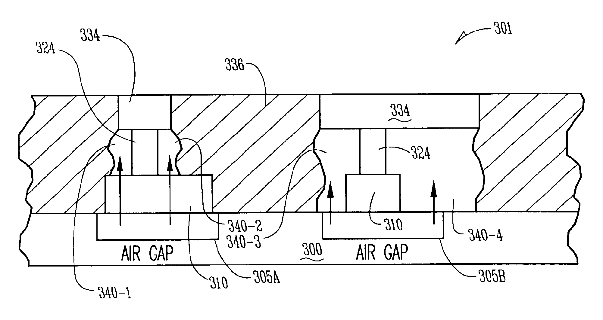
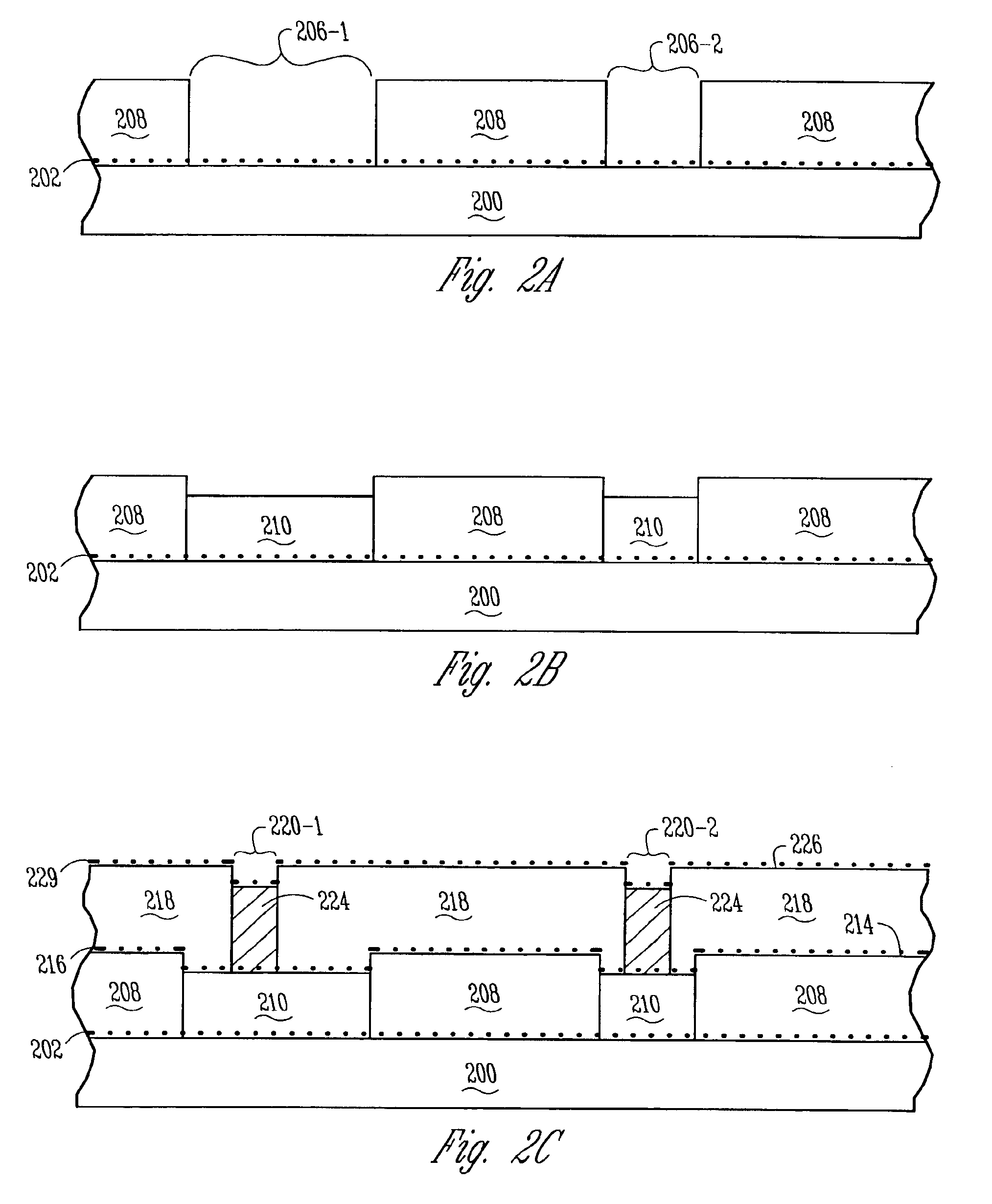
Structures and methods are provided for an improved multilevel wiring interconnect in an integrated circuit assembly. The present invention provides for a multilayer copper wiring structure by electroless, selectively deposited copper in a streamlined process which further reduces both intra-level line to line capacitance and the inter-level capacitance.In particular, an illustrative embodiment of the present invention includes a novel methodology for forming multilevel wiring interconnects in an integrated circuit assembly. The method includes forming a number of multilayer metal lines, e.g. copper lines formed by selective electroless plating, separated by air gaps above a substrate. A low dielectric constant material is deposited between the number of metal lines and the substrate using a directional process. According to the teachings of the present invention, using a directional process includes maintaining a number of air gaps in the low dielectric constant material. Structures and systems are similarly included in the present invention.

Description

RELATED APPLICATIONS[0001]This application is a Divisional of U.S. Ser. No. 09 / 583,514 filed on May 31, 2000, U.S. Pat. No. 6,423,629 which is incorporated herein by reference.[0002]This application is related to the following co-pending and commonly assigned application; application Ser. No. 09 / 483,881, entitled “Selective Electroless-Plated Copper Metallization,” which is hereby incorporated by reference.FIELD OF THE INVENTION[0003]The present invention relates generally to integrated circuits. More particularly, it pertains to structures and methods for multilevel copper interconnects with low-k dielectric constants and air gaps.BACKGROUND OF THE INVENTION[0004]As the integrated circuit (IC) technology makes rapid progress toward 100 nm gate transistors, the speed limiting factor is no longer the transistor delay, but the RC delay associated with the metal interconnects. A great deal of work is being done in this area on new and innovative materials and fabrication techniques to ...

Claims


Application Information

Patent Timeline
Patent Type & Authority Patents(United States)
IPC IPC(8): H01L23/52H01L23/48H01L21/4763H01L21/768H01L23/522H01L23/532
CPCH01L21/7682H01L21/76879H01L21/76885H01L23/5222H01L23/53238H01L23/53295H01L2924/0002H01L2924/00
Inventor AHN, KIE Y.FORBES, LEONARD
Owner ROUND ROCK RES LLC
Learn More