AC generator for vehicle having rectifying unit

a technology of rectifying unit and ac generator, which is applied in the direction of dynamo-electric converter control, magnetic circuit shape/form/construction, rotating parts of magnetic circuit, etc., can solve the problems of increasing the temperature of the engine compartment, increasing the power consumption of the vehicle, and increasing the temperature of various parts, so as to reduce the temperature rise of the rectifying unit and reduce the production cost. , the effect of reducing the temperature ris

Inactive Publication Date: 2006-08-15
DENSO CORP
View PDF26 Cites 0 Cited by
  • Summary
  • Abstract
  • Description
  • Claims
  • Application Information

AI Technical Summary

Benefits of technology

[0017]In order to attain the above described subjects, an ac generator for a vehicle includes a rotor for providing a rotating magnetic field, a stator disposed around said rotor and having a stator core in which a plurality of phase-windings is mounted to generate electromotive force when the rotating magnetic field is supplied, a rectifying unit formed by a bridge circuit which includes a plurality of pairs of a positive electrode side rectifying element and a negative side rectifying element respectively connected to the plurality of phase-windings. It is characterized in that one of the pairs of the positive electrode side rectifying element and negative electrode side rectifying element that is connected to at least a portion of the plurality of phase-windings is constituted of a single diode and the remainder is constituted of parallelly connected two diodes. Because one of the positive electrode side rectifying element and the negative electrode side rectifying element is constituted of parallelly connected two elements that corresponds to each phase-winding, particularly phase-current passing through a diode that is disposed at a portion whose temperature is very high is shared by two elements to suppress temperature rise thereof. Because the heat generating elements can be separately disposed on the heat sink of the rectifying unit, the temperature rise of the rectifying unit can be reduced.
[0018]It is preferable that the above described diodes that constitute the positive electrode side rectifying elements and the negative electrode side rectifying elements are zener diodes. Because the zener diode timely breaks down when a surge voltage is generated in the phase winding, surge voltage emission from the ac generator may be prevented. Further, parallelly connected zener diodes are used for only a portion of the rectifying elements of the rectifying unit, the production cost can be made comparatively less.
[0019]It is preferable that one of the parallelly connected two elements is a zener diode and the other is a normal diode. If a surge voltage is generated in a phase winding, the zener diode timely breaks down, so that a surge voltage emission from the ac generator can be prevented. Use of the normal diode can reduce the production cost.
[0020]It is preferable that each of the parallelly connected two elements has a smaller current capacity than other elements, because such elements are less expensive than other elements of a normal current capacity.
[0021]It is also preferable that a positive electrode side heat sink to which the positive electrode side rectifying elements are fixed and a negative electrode side heat sink to which the negative electrode side rectifying elements are fixed are disposed in two planes that are perpendicular to a rotation axis of said rotor, and that one of the positive electrode side heat sink and the negative electrode side heat sink that is larger in outside diameter than the other is constituted of a plurality of separate heat sinks. The above arrangement increases the yield ratio of heat sink material, thereby reducing the material cost.
[0022]It is preferable that the parallelly connected two elements are respectively fixed to each of the plurality of separate heat sinks. This arrangement can uniformly reduce the temperature of the respective heat sinks and prevent the local temperature rise of the rectifying unit from becoming very high. If three phase-windings are used in the ac generator, the parallelly connected two elements are used to correspond to one of the phase-windings, and four elements are used as the positive electrode side rectifying elements or negative electrode side rectifying elements. In this case, the same number of elements can be allocated to each separate heat sink, so that difference in temperature between the separate heat sinks is small.

Problems solved by technology

Accordingly, power consumption of the vehicle has increased and heat generation by the ac generator increases, so that temperature of various parts becomes very high.
Further, the increase in the various electrical accessories increases the degree of accumulation of the engine compartment, resulting in increasing the temperature of the engine compartment.
In such a vehicle, if a surge voltage is generated by the ac generator due to breakdown of a power line of the ac generator or abrupt shutdown of an electric load, the ECU or other devices may fail.
Therefore, the heat transfer from the negative electrode side heat sink is not effectively carried out.
In other words, a sufficient cooling effect can not be achieved.
However, a sufficient cooling effect can not be provided because the temperature of the housing becomes very high, as stated above.
The positive electrode side heat sink does not particularly increase the cooling effect, resulting in insufficient cooling.
However, the zener diode is more expensive than the normal diode, resulting in increase in the cost of the ac generator.
In this rectifying unit, a high backward voltage may be applied to the normal diodes, so that a surge voltage may go out of an ac generator to an electronic device such as an ECU, which may be badly affected.
The rectifying unit disclosed in JP-B2-4-24945 has much more rectifying elements, and it is difficult to reduce the size and weight of an ac generator for a vehicle and the production cost thereof.

Method used


Image

  • AC generator for vehicle having rectifying unit
  • AC generator for vehicle having rectifying unit
  • AC generator for vehicle having rectifying unit

Examples


Embodiment Construction

[0035]An ac generator for a vehicle according to a preferred embodiment of the invention will be described with reference to the appended drawings.

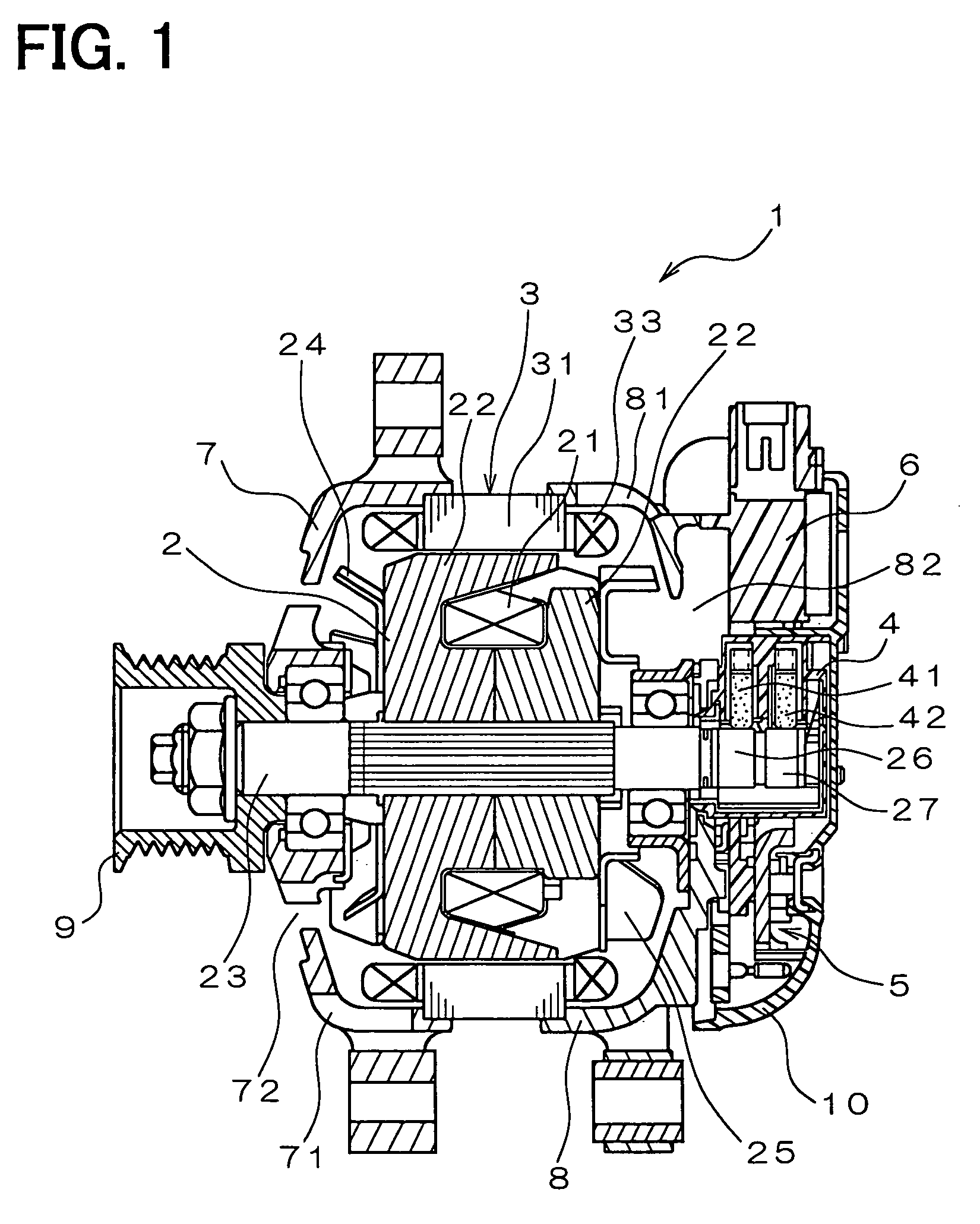
[0036]FIG. 1 is a cross-sectional view of an entire body of the ac generator for a vehicle according to the preferred embodiment of the invention, which has an internal cooling fan. As shown in FIG. 1, the vehicle ac generator 1 includes a rotor 2, a stator 3, a brush unit 4, a rectifying unit 5, an IC regulator 6, a drive frame 7, a rear frame 8, a pulley 9, a rear cover 10, etc.

[0037]The rotor 2 has a field coil 21 of a cylindrically wound insulated copper wire and a pair of pole cores 22 each of which is fixed together by a rotary shaft 23 to sandwich the field coil and has six claw poles surrounding the field coil 21. An axial flow type cooling fan 24, which takes in air from a front portion of the ac generator and sends out the air in axial and radial directions, is fixed by welding or the like to the front one of the pole cores 22 a...


PUM


Abstract

An ac generator for a vehicle includes a rotor for providing a magnetic field, a stator having a stator core in which a plurality of phase-windings is mounted to generate electromotive force when the magnetic field is supplied, a rectifying unit which includes positive electrode side rectifying elements and negative electrode side rectifying elements respectively connected to the plurality of phase-windings. One of the positive electrode side rectifying element and negative electrode side rectifying element that is connected to a portion of the phase-windings is constituted of a single element and the remainders are constituted of parallelly connected two elements.

Description

CROSS REFERENCE TO RELATED APPLICATION[0001]The present application is based on and claims priority from Japanese Patent Application 2002-368284, filed Dec. 19, 2002, the contents of which are incorporated herein by reference.BACKGROUND OF THE INVENTION[0002]1. Field of the Invention[0003]The present invention relates to an ac generator for a vehicle to be mounted in a vehicle or the like.[0004]2. Description of the Related Art[0005]An ac generator for a vehicle generates electric power by means of mechanical power that is supplied by an engine so as to charge a battery and supply electric power for engine ignition, illumination and operation of various electrical accessories. It is very important to make such an ac generator more compact, lighter in weight, more powerful and less expensive, in view of market competition.[0006]Recently, various electric accessories have been adopted in order to comply with various laws and regulations and market demand for more sophisticated vehicle...

Claims


Application Information

Patent Timeline
Patent Type & Authority Patents(United States)
IPC IPC(8): H02K7/00H02K9/06H01L25/07H02K11/04H02M7/06
CPCH02K11/046H01L25/072H01L2224/45147H01L2924/00014H01L2924/00H01L2224/48H02K11/05H02M7/06
Inventor OGI, HIROYUKI
Owner DENSO CORP
Why Eureka
Try Eureka