Integrated hover display with augmented approach to hover symbology cueing for degraded visual environmental conditions

a technology of visual environment conditions and integrated display, which is applied in the direction of navigation instruments, instruments, process and machine control, etc., can solve the problems of rotary wing aircraft becoming engulfed in a cloud of visually restricted materials, affecting the appearance of dve conditions, etc., to facilitate the approach, hover and landing

Active Publication Date: 2006-08-15
SIKORSKY AIRCRAFT CORP
View PDF13 Cites 52 Cited by
  • Summary
  • Abstract
  • Description
  • Claims
  • Application Information

AI Technical Summary

Benefits of technology

[0010]An integrated display system according to the present invention may include a primary flight display having a hover display which facilitates operations in a DVE condition. The hover display may include a radar altitude display, heading drift symbology and lateral drift symbology.
[0014]The heading draft symbology and the lateral drift symbology as described herein assists pilots in the detection of drift, which is common in DVE situations, to provide the pilot with a salient cue pertinent to the approach to hover and landing.

Problems solved by technology

Often the topography, ground hazards, obstacles and weather in the area are unknown or changing.
If the terrain condition is such that dust, snow, sand, or the like will be stirred by rotor downwash, the rotary wing aircraft may become engulfed in a cloud of visually-restrictive material.
Research including literature reviews, pilot interviews, and military incident reports indicate that incidents due to DVE conditions often occur because the pilot becomes spatially disoriented due to loss of visual references.
Such an increase in workload further complicates tactical situations.
Pitot static sensors provide information relative to air mass and may be inaccurate at low speed due to the influence of rotor downwash.
Furthermore, as the terrain itself may be uneven and cloaked due to the DVE condition, the pilots burden of assuring that the landing gear settles without undue lateral rolling of the aircraft at touchdown is further complicated.
Fore, aft, lateral, and heading drift are also components that may increase spatial disorientation in DVE situations.
Conventional hover displays fail to provide cuing symbology that effectively displays such drift components.
Although rotary wing aircraft are effectively operated in DVE conditions, conventional displays have, however, heretofore not provided an integrated hover display which significantly minimizes the potential for spatial disorientation in a DVE condition.

Method used


Image

  • Integrated hover display with augmented approach to hover symbology cueing for degraded visual environmental conditions
  • Integrated hover display with augmented approach to hover symbology cueing for degraded visual environmental conditions
  • Integrated hover display with augmented approach to hover symbology cueing for degraded visual environmental conditions

Examples


Embodiment Construction

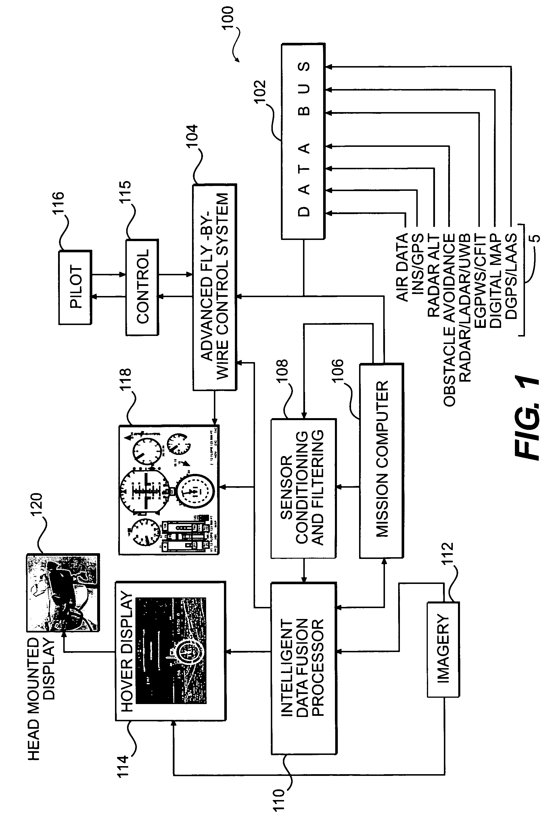
[0033]FIG. 1 illustrates a general system architecture block diagram view of a flight control system 100 which facilitates operations in a degraded visual environment (DVE). Preferably, the flight control system 100 includes a plurality of interconnected systems to assist a pilot in operating a rotary wing, vertical take off and landing (VTOL), aircraft. Typically, the systems include FBW flight control, display, sensor, imagery, navigation, data fusion, processing, and control.

[0034]As described in greater detail below, the flight control system 100 may include a data bus 102 with inputs from a sensor system S, a mission computer 106, intelligent data fusion processor 110, a sensor conditioning and filtering system 108, a fly by wire (FBW) flight control system 104, and an imagery system 112.

[0035]The sensor system S may include a variety of sensors for surveying the environment and providing information to the pilot to augment the pilot's visual cues. This environmental informatio...


PUM


Abstract

A flight control system includes a primary flight display having a hover display which facilitates operations in DVE conditions. The hover display includes a radar altitude display, heading drift symbology and lateral drift symbology which assists pilots in the detection of drift, which is common in DVE situations and to provide the pilot with a salient cue pertinent to the approach to hover and landing.

Description

[0001]The present application is a Continuation-in-Part application of U.S. patent application Ser. No. 10 / 816,218, filed Mar. 31, 2004, which claims priority to U.S. Provisional Patent Application Ser. No. 60 / 458,257, dated Mar. 31, 2003.BACKGROUND OF THE INVENTION[0002]The present invention relates to instrumentation for a rotary wing aircraft, and more particularly to an integrated hover display to provide a pilot with augmented symbology cueing which facilitates approach and landing when visually-restrictive conditions are encountered.[0003]Rotary wing aircraft are routinely required to approach and land at remote sites without navigation guidance or acceptable visual conditions. Often the topography, ground hazards, obstacles and weather in the area are unknown or changing. Upon arrival at the remote site, the pilot must typically make critical judgments based on incomplete or inaccurate data in order to determine the proper procedure to approach and land. If the terrain condit...

Claims


Application Information

Patent Timeline
Patent Type & Authority Patents(United States)
IPC IPC(8): G01C21/00H04L29/06H04L29/08
CPCG01C23/00G08G5/0095H04L67/125H04L29/06H04L69/329G05D1/102H04L9/40
Inventor JUDGE, JOHN H.OCCHIATO, JOHN J.STILES, LORRENSAHASRABUDHE, VINEETMACISAAC, MARGARET A.
Owner SIKORSKY AIRCRAFT CORP
Why Eureka
Try Eureka