Sampling apparatus for material collection

Active Publication Date: 2006-08-22
GLOBAL LIFE SCI SOLUTIONS USA LLC
View PDF13 Cites 23 Cited by
  • Summary
  • Abstract
  • Description
  • Claims
  • Application Information

AI Technical Summary

Benefits of technology

[0007]The present invention allows the user to withdraw a sample from a source and retain it within the tubular sample sleeve until needed. Suitable sample sources for this invention include soft materials such as cloth, paper, wood, films, gels, plant, animal and human tissues, and other sources capable of being cut by a surgical steel cutting edge. Ejection of the sample in increments allows for small portions of the sample to be segmented from the whole of the sample without removal of the entire sample from the cutting sleeve. Using this technique reduces likelihood for inadvertent or accidental cutting and

Problems solved by technology

Removal of sample from the cutting sleeve in either method as described above, presents a number of problems that may affect the integrity of the sample.
Moreover, sample handling may present potential health hazards to the technician working with the sample.
The process of picking a sample from the cutting sleeve is inefficient and time consuming.
The

Method used


Image

  • Sampling apparatus for material collection
  • Sampling apparatus for material collection
  • Sampling apparatus for material collection

Examples


Embodiment Construction

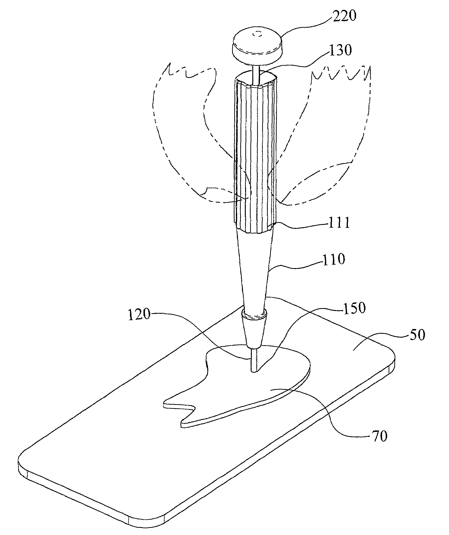
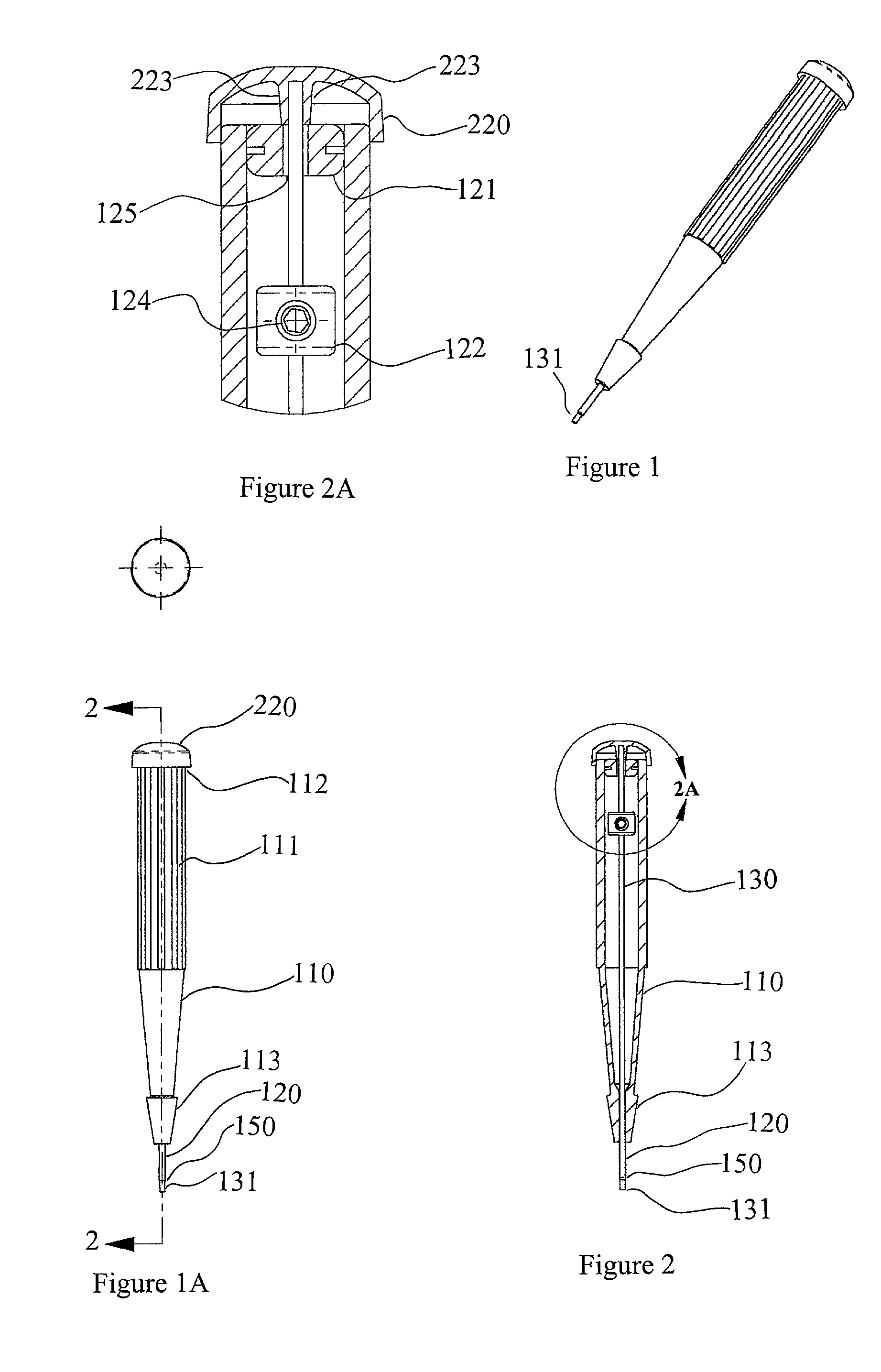
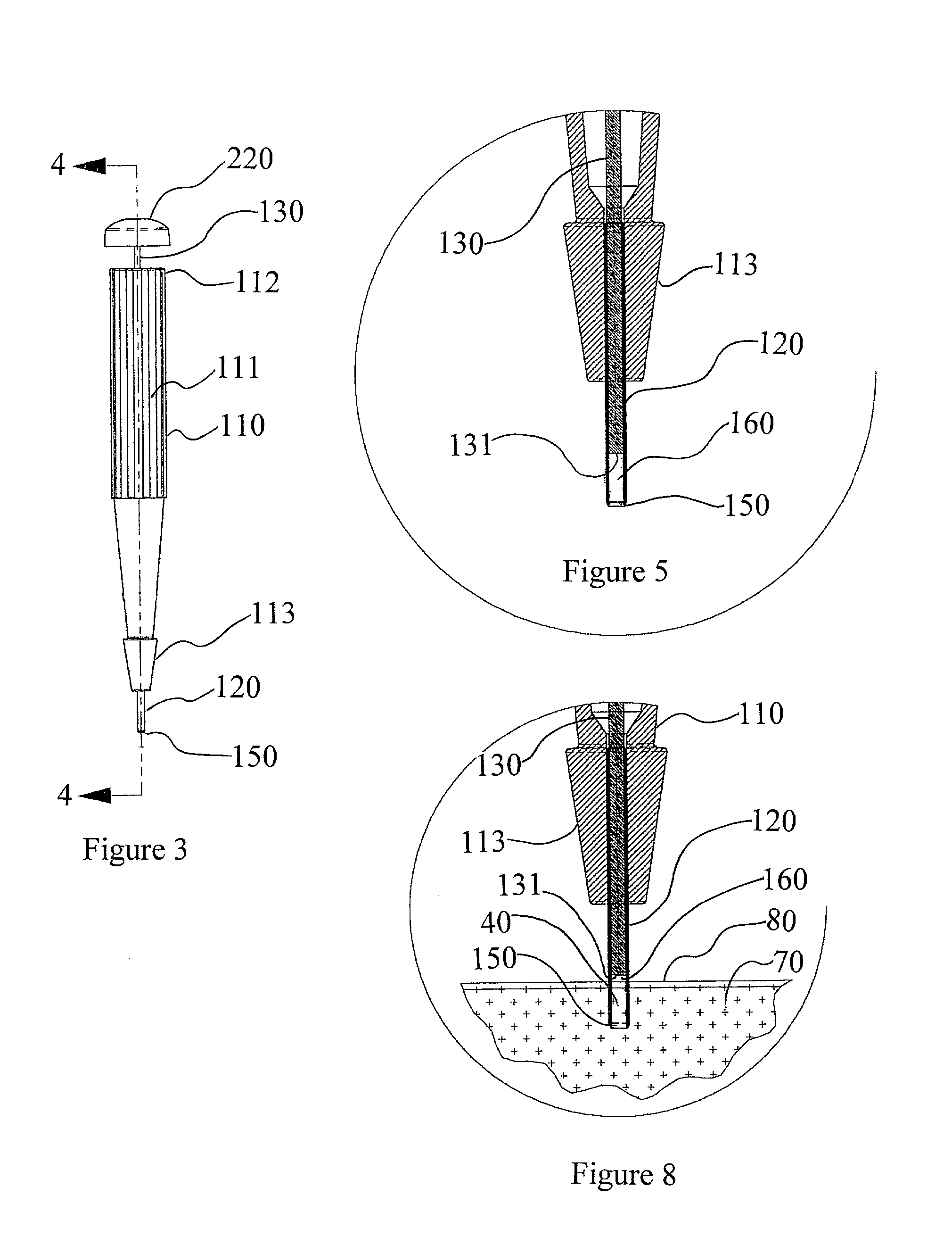
[0030]Referring to FIGS. 1 and 1A, a preferred embodiment of a sample collection device constructed in accordance with the principles of the invention is shown. A handle 110 has a tubular sample sleeve 120 extending from one end of the handle 110 indicated by 113. The exterior surface of the handle may include a plurality of ridges 111 to provide a better gripping surface for the user. There is a plunger 131 shown here in an expulsion position, where the plunger 131 extends past cutting edge 150 of tubular sample sleeve 120.

[0031]FIG. 2 and shows a longitudinal cross-section of the device taken along cutting line 2—2 of FIG. 1A. A linkage 130 connects plunger 131 to an actuator, shown here as cover 220, which axially reciprocates plunger 131 through the lumen of sleeve 120 between an expulsion position, as shown in FIGS. 1, 1A and 2, and a retracted position as shown in FIGS. 3 and 4. The retracted position has plunger 131 positioned within the apparatus and preferably within tubula...


PUM


Abstract

An apparatus to collect a sample of material has a handle with a tubular sample sleeve extending from an end of the handle. The end of the sleeve distal from the handle forms a cutting edge circumscribing a circular sampling region. A plunger slides reciprocally within the tubular sample sleeve between a retracted position and an expulsion position. A user cuts a sample from a source material by engaging contact between the cutting edge of the tubular sample sleeve and the source material. The sample cut from the source is lodged within the tubular sample sleeve. Actuation of the plunger from the retracted position toward the expulsion position displacing the sample from the sleeve.

Description

BACKGROUND OF THE INVENTION[0001]1. Field of Invention[0002]The invention relates to the field of micro-sampling for the collection of in situ material such as human tissue, field samples for related environmental examination, crime scene sampling, or other related materials or material prepared on a substrate and then sampled such as dried blood on a blood card. Sampling regimes are designed to extract a micro-sample from a larger source sample material. The micro-samples extracted may be chemically analyzed for the purposes of DNA analysis, nondestructively analyzed by placement on the appropriate spectra generating sample stage or observed under microscopic conditions.[0003]2. Description of Prior Art[0004]Sampling devices are conventionally used to extract samples from materials such as paper, cloth, wood, tissues and the like. In one arrangement, a sampling device has a tubular sleeve forming a cutting edge at one end. A sample is obtained by advancing the sleeve into the sampl...

Claims


Application Information

Patent Timeline
IPC IPC(8): G01N1/04B01L99/00G01N1/00G01N1/02G01N1/08
CPCB01L99/00G01N1/08B01L2400/0478Y10T436/25375G01N2001/028Y10S83/919Y10T436/25G01N2001/007
Inventor HARRIS, JOEL STEVEN
Owner GLOBAL LIFE SCI SOLUTIONS USA LLC
Why Eureka
Try Eureka