Control of autoignition timing in a HCCI engine

a technology of autoignition timing and internal combustion engine, which is applied in the direction of electrical control, machines/engines, non-mechanical valves, etc., can solve the problems of increased heat transfer loss, increased co emissions, and combustion noise, and reduce combustion efficiency

Inactive Publication Date: 2006-08-22
FORD GLOBAL TECH LLC
View PDF15 Cites 46 Cited by
  • Summary
  • Abstract
  • Description
  • Claims
  • Application Information

AI Technical Summary

Benefits of technology

[0014]In an illustrative embodiment of the invention, the exhaust valve timing is substantially fixed before TDC over successive engine cycles to control the air-fuel ratio in the combustion chamber. The opening time of the intake valve is varied relative to TDC (e.g., advanced toward TDC) over successive intake cycles in a manner that changes the temperature of the fresh air / residual burned gas mixture in the combustion chamber into which the fuel is mixed and thus the autoignition timing. The exhaust valve timing and / or the fuel injection pulse width can be adjusted slightly to compensate for the effect of the temperature change of the mixture on the mass of the inducted fresh air in the combustion chamber. Further, for each intake event, an initial intake valve opening event preferably is provided immediately after the exhaust valve closes and before TDC followed by a main intake valve event occurring after TDC in a manner to reduce or minimize engine pumping losses.
[0015]In another illustrative embodiment of the invention, the intake valve lift timing is substantially fixed after TDC over successive engine cycles to control the air-fuel ratio in the combustion chamber. The closing time of the exhaust valve is varied relative to TDC (e.g., retarded toward TDC) over successive exhaust cycles in a manner that changes the temperature of the fresh air / residual burned gas mixture in the combustion chamber into which fuel is mixed and thus the autoignition timing. The intake valve timing and / or the fuel injection pulse width can be adjusted as needed in order to compensate for the effect of the temperature change of the mixture on the mass of the inducted fresh air in the combustion chamber. For each exhaust event, a first main exhaust valve opening event preferably is provided before TDC followed by a subsequent secondary exhaust valve event occurring after TDC immediately before opening of the intake valve in a manner to reduce or minimize engine pumping losses.

Problems solved by technology

Control of autoignition timing in an HCCI engine is more difficult than in a diesel engine, which controls fuel injection timing to control autoignition timing.
For example, at higher torque, autoignition timing tends to advance, resulting in the increase in heat transfer losses, NOx emissions, and combustion noise.
At lower engine torque, autoignition timing tends to be retarded, resulting in an increase of CO emissions and lower combustion efficiency.
However, use of negative valve overlap as a single control variable in HCCI engine control strategy to control both the autoignition timing and the air-fuel ratio at different operating conditions is problematic in that use of a single negative valve overlap variable in the control strategy offers insufficient degrees of freedom to control the air-fuel ratio, in-cylinder gas temperature, and residual fraction of burned gas in the in-cylinder gas in a manner to provide favorable values for all of these parameters at different operating conditions.

Method used


Image

  • Control of autoignition timing in a HCCI engine
  • Control of autoignition timing in a HCCI engine
  • Control of autoignition timing in a HCCI engine

Examples


Embodiment Construction

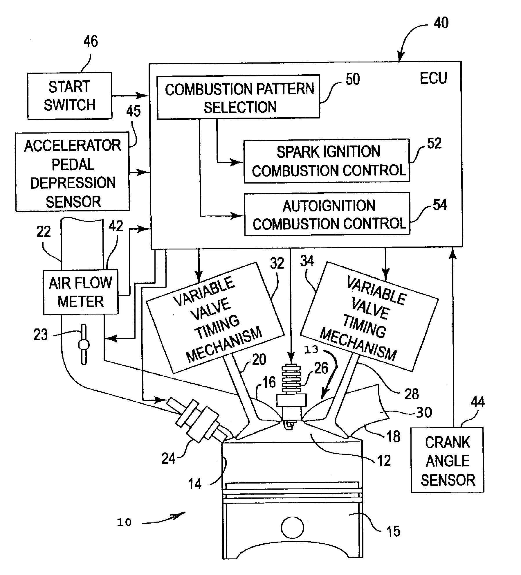
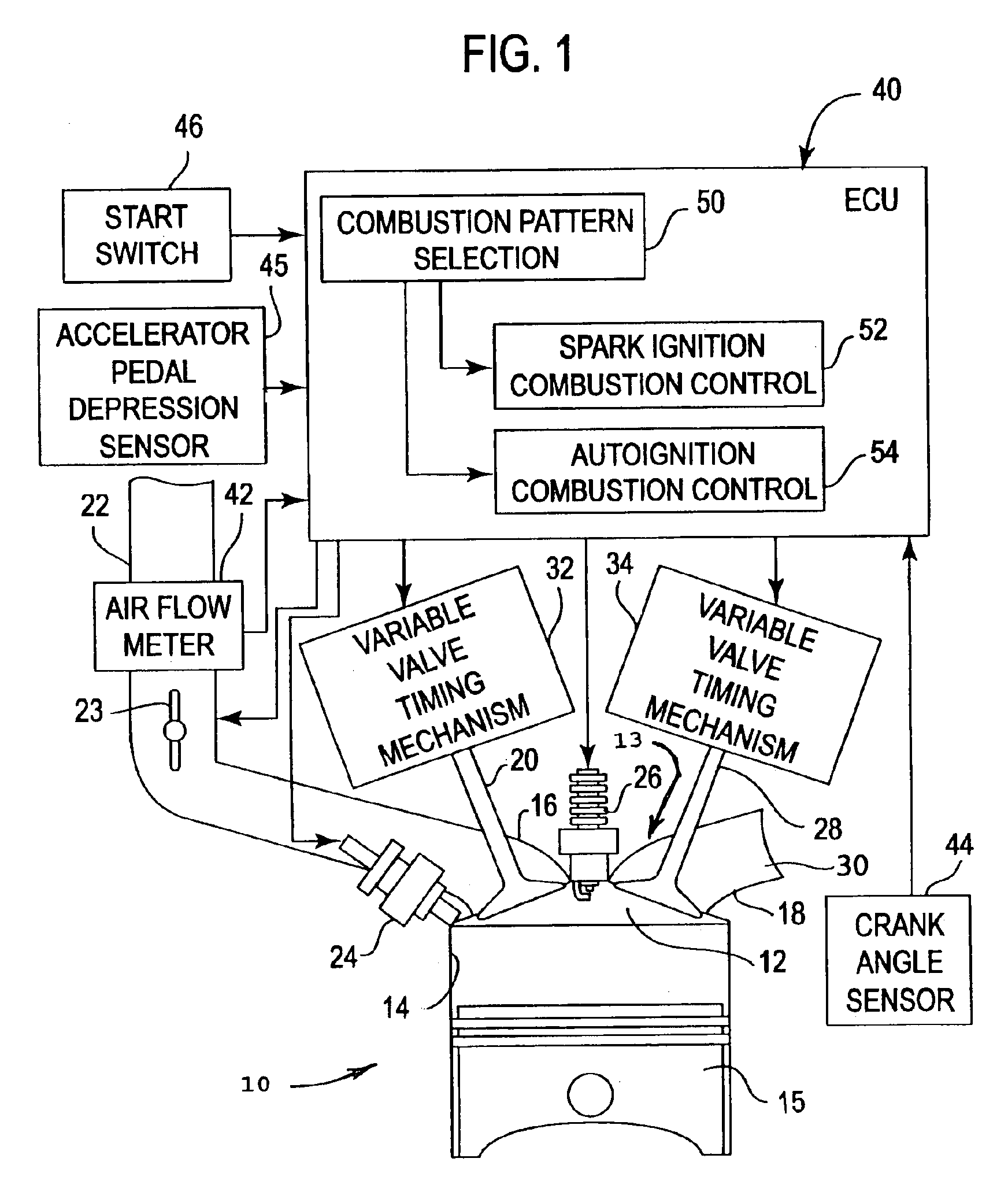
[0022]Referring to FIG. 1, a four cycle internal combustion engine 10 is illustrated as comprising a combustion chamber 12 formed by a conventional cylinder head 13, cylinder 14, and piston 15. The combustion chamber 12 is expanded and contracted by the piston 15 reciprocating in the engine cylinder 14. An intake port 16 and exhaust port 18 of the engine 10 communicate with the combustion chamber 12 in conventional manner. An intake valve 20 is provided in the intake port 16. An intake passage 22 of the engine communicates with the intake port 16. Air is aspirated from the intake passage 22 through the intake port 16 into the combustion chamber 12 when the intake valve 20 is open due to the piston descending in the cylinder. A throttle 23 is provided in intake passage 22 for adjusting the intake air flow rate of the engine in a spark ignition (SI) mode. In HCCI mode, the throttle 23 is preferably fully open as shown in FIG. 1. A conventional fuel injector 24 and spark plug 26 are pr...


PUM


Abstract

Method and system embody a valve timing strategy to control the autoignition timing of a four stroke internal combustion engine (10) operated in an HCCI mode at different engine operating conditions such as different engine speed and torque. A particular valve timing strategy varies lift timing of the intake valve (20) relative to the exhaust valve (28), or vice versa, and relative to top dead center in response to a change in engine torque, for example, to vary amount of trapped residual burned gas in the combustion chamber (12) flowing to an intake or exhaust port (16,18) and back to the combustion chamber during which the residual gas is cooled. Control of the flow of residual gas between the combustion chamber and intake or exhaust port and thus its temperature by the valve timing strategy, in turn, is used to control the temperature of the fresh air / residual gas / fuel mixture in the combustion chamber (12) and thus autoignition timing in response to a change in engine torque.

Description

CROSS-REFERENCE TO RELATED APPLICATIONS:[0001]This application is a continuation of U.S. Patent Application Ser. No. 10 / 248,349, filed Jan. 13, 2003. As such, the present application claims priority to an original filing date of Jan. 13, 2003. The original patent application is herein incorporated by reference in its entirety for all purposes.BACKGROUND OF INVENTION[0002]1. Field of the Invention[0003]This invention relates to methods and systems for controlling autoignition timing of an internal combustion engine operated in a homogeneous-charge compression-ignition mode.[0004]2. Background Information[0005]A conventional gasoline-fueled internal combustion engine employs spark ignition where the fuel and air are premixed and a spark initiates a flame that propagates through the fuel / air mixture in the combustion chamber. The other common type of internal combustion engine employs compression ignition where the fuel and air are purposely kept separate until shortly before top dead ...

Claims


Application Information

Patent Timeline
Patent Type & Authority Patents(United States)
IPC IPC(8): F02B1/12F02D13/02F02D41/30
CPCF02B1/12F02D13/0207F02D13/0215F02D13/0265F02D41/3035F02D13/0273Y02T10/18F02D2041/001Y02T10/128Y02T10/12
Inventor YANG, JIALIN
Owner FORD GLOBAL TECH LLC
Why Eureka
Try Eureka