Subsea production system

a production system and subsea technology, applied in the direction of filtration separation, separation process, borehole/well accessories, etc., can solve the problems of pressure drop, water generation several problems, and normal oil not being achieved,

Inactive Publication Date: 2006-08-22
AKER SUBSEA LTD
View PDF38 Cites 128 Cited by
  • Summary
  • Abstract
  • Description
  • Claims
  • Application Information

AI Technical Summary

Benefits of technology

[0032]The present invention takes advantage of the newest developments in tree technology, to make it possible to produce and inject (including power fluid supply) through the same x-mas tree. However, the present invention is not limited to the use of the above mentioned trees, since it is also possible to realise the invention through more conventional technology.
[0033]The main object of the present invention is to facilitate the supply of power fluid to downhole turbines or engines in a plurality of wells, and further facilitate the control of downhole separators.
[0034]A further object of the present invention is to enable an accommodation of the equipment to the changing requirement over the lifespan of the well, e.g. enable transportation of produced hydrocarbons in both headers in the beginning of the lifespan and enable water injection through one header when the wells are producing increasingly larger ratios of water.
[0035]Another object of the present invention is to reduce costs by reducing the need for equipment, and thereby also reducing the installation costs and service costs.
[0036]A further object of the present invention is to make it possible to use only one flowline coupled to the subsea manifold, whilst still retaining the possibility of supplying power fluid to turbines in the wells.

Problems solved by technology

Water generates several problems for the oil and gas production process.
However, pure oil will normally not be achieved by use of cyclones.
Furthermore, energy is taken from the well fluid and is consumed for setting up a centrifugal field within the cyclones, thereby creating a pressure drop.
Limited operational time of a downhole ESP is largely caused by failure in power cable, electrical connections and electrical motors.
The energy required for lifting produced liquid to the seabed will result in a substantial pressure drop in the production tubing.
When considerable volume of gas is present in the wellbore a oil-water separator will have reduced capacity and separation performance will decline.
A gravity separator may be used, but will be ineffective when liquid is in form of mist carried with the high velocity gas flow.
These demands and requirements may very often vary over time.
At long tie-back distances the net effect of using gas lift becomes low when gain in static pressure is reduced by increased dynamical pressure losses.

Method used


Image

  • Subsea production system
  • Subsea production system
  • Subsea production system

Examples


Embodiment Construction

[0065]For the description of all embodiments hereafter the features corresponding fully with the previous embodiment, or embodiment referred to, is not described in detail. It is to be understood that the parts of the embodiment not described in detail fully complies with the previous embodiment or any other embodiment referred to.

[0066]When in the following specification the term well fluid is used, this means the fluid that is extracted from the formation. The well fluid may contain gas, oil and / or water, or any combinations of these. When in the following specification the term production fluid is used, this means the portion of the well fluid that is brought from the reservoir to the seabed.

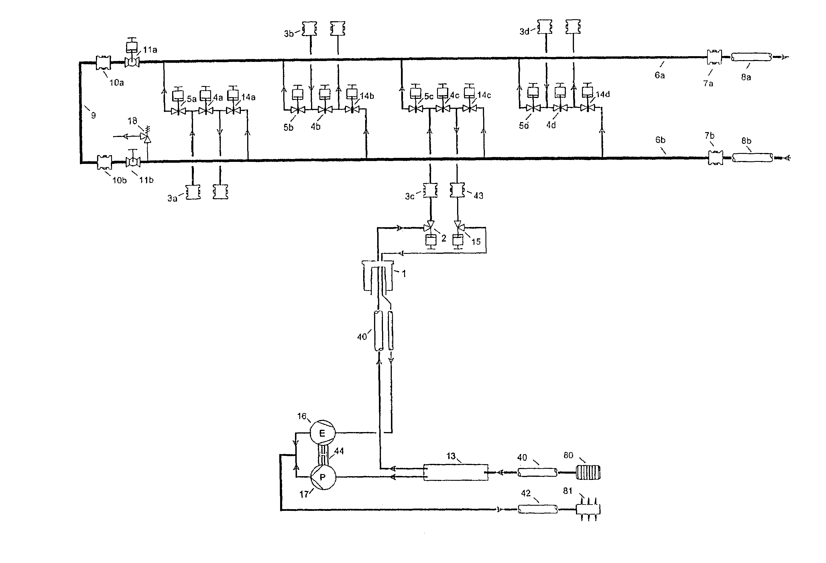
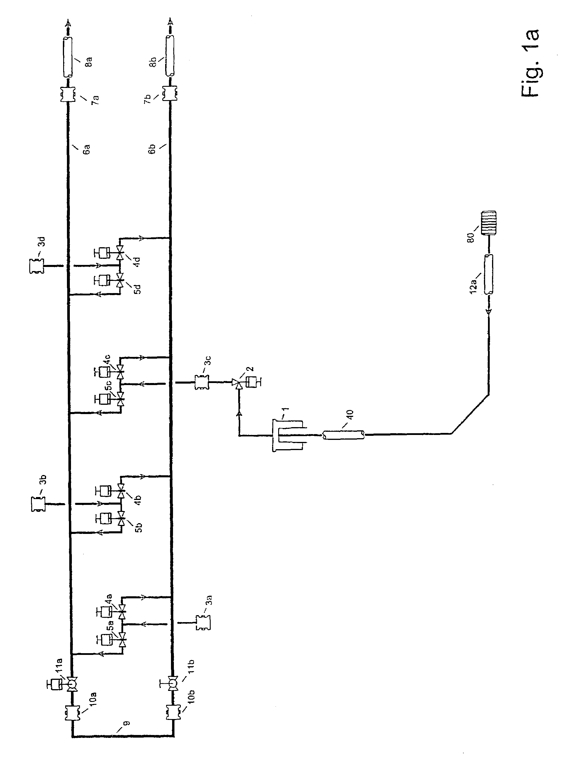
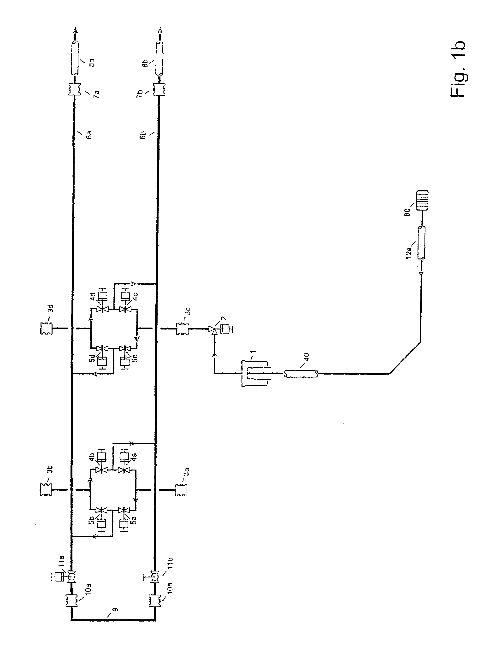
[0067]FIG. 1a illustrates a prior art production situation layout with four wells, each connected to the manifold by mechanical connectors 3a, 3b, 3c, 3d. For illustration the well connected to the mechanical connector 3c the layout is displayed in detail. However, it should be understood tha...


PUM

PropertyMeasurementUnit
pressureaaaaaaaaaa
poweraaaaaaaaaa
electricaaaaaaaaaa

Abstract

Methods and arrangements for production of petroleum products from a subsea well. The methods comprise control of a downhole separator, supplying power fluid to a downhole turbine / pump hydraulic converter, performing pigging of a subsea manifold, providing gas lift and performing three phase downhole separation. Arrangement for performing the methods are also described.

Description

RELATED APPLICATIONS[0001]This application is a National Phase entry in the United States of the International Application No. PCT / NO01 / 00086, filed Mar. 5, 2001 and claims the benefit of the Norwegian Application 2000 1446, filed Mar. 20, 2000.BACKGROUND OF THE INVENTION[0002]1. Field of the Invention[0003]The invention relates to a method of controlling a downhole separator for separating hydrocarbons and water such that the hydrocarbons leave the separator flowing through a x-mas tree and a first header in a manifold, where a power fluid is used to drive a downhole turbine / pump hydraulic converter, such that the pump in the downhole turbine / pump hydraulic converter pumps separated water, and where the power fluid for the downhole turbine / pump hydraulic converter is fed through a second header in the manifold, an adjustable valve and the x-mas tree to the turbine in the downhole turbine / pump hydraulic converter. The rate of pumping is controlled by the rate of power fluid based on...

Claims


Application Information

Patent Timeline
Patent Type & Authority Patents(United States)
IPC IPC(8): E21B29/12E21B37/00E21B43/01E21B43/017E21B43/12E21B43/38
CPCE21B37/00E21B43/01E21B43/385E21B43/129E21B43/017E21B43/13
Inventor OLSEN, GEIR INGE
Owner AKER SUBSEA LTD
Why Eureka
Try Eureka