Method of and apparatus for friction stir welding

Inactive Publication Date: 2006-08-22
HONDA MOTOR CO LTD
View PDF22 Cites 6 Cited by
  • Summary
  • Abstract
  • Description
  • Claims
  • Application Information

AI Technical Summary

Benefits of technology

[0021]A general object of the present invention is to provide a method of and an apparatus for friction stir welding in which especially thin plate members are joined to one another and any unjoined portion is reliably removed to successfully maintain joining strength.
[0022]A principal object of the present invention is to provide a method of and an apparatus for friction stir welding in which the process is economical and the occurrence of residual strain can be effectively avoided.
[0023]Another object of the present invention is to provide a method of and an apparatus for friction stir welding in which any unjoined portion can be reliably removed and the strength of the joined portion is effectively increased, making it possible to improve the reliability.
[0024]Still another object of the present invention is to provide a method of and an apparatus for friction stir welding in which no residual strain appears in a first plate member and a second plate member when a backing jig and a buffer member are disengaged.
[0025]Still another object of the present invention is to provide a method of and an apparatus for friction stir welding in which the dimensional accuracy of the product is improved and the friction stir welding process can be efficiently carried out.

Problems solved by technology

If the welding is performed by means of the conventional spot welding or the conventional electron beam welding by using an aluminum material as the workpiece, for example, some excessive heat is applied to the aluminum material.
Therefore, the strength may be decreased due to deterioration of the material and / or change of crystals into coarse microstructure.
On the other hand, if light weight is desired as well as the improvement of strength in the case of gas turbine engine members or the like, it is difficult to increase the thickness of each component.
However, when an abutment portion, at which both ends of thin plate-shaped aluminum materials are butted together, is joined by means of FSW to form a cylindrical member having a relatively large diameter, it is difficult to obtain a satisfactory circularity or roundness because the aluminum material is thin.
Furthermore, when the aluminum material is thin plate, unjoined portion tends to appear when the abutment portion is joined by FSW.
As a result, the frictional heat is insufficient, and the unjoined portion U appears.
Because the unjoined portion U may be a fracture origin, structural reliability is deteriorated.
Therefore, it is not economical.

Method used


Image

  • Method of and apparatus for friction stir welding
  • Method of and apparatus for friction stir welding
  • Method of and apparatus for friction stir welding

Examples


Embodiment Construction

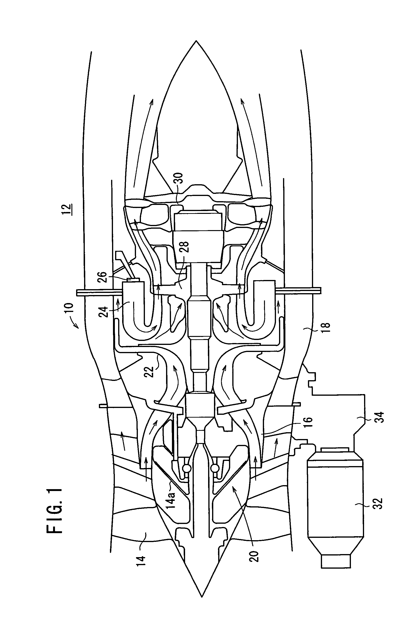
[0048]FIG. 1 schematically illustrates a structure of a gas turbine engine 12 for an airplane into which a fan duct 10 is incorporated. A friction stir welding method according to a first embodiment of the present invention is carried out especially for the fan duct 10.

[0049]The gas turbine engine 12 is provided with a fan 14. The fan 14 is rotated at a high speed to suck the air from the outside. The air is compressed, and fed to the backward under pressure. A fan bypass passage 18 is formed by a core duct 16 and the fan duct 10 in the vicinity of the fan 14. A thrust force is generated for an unillustrated airframe by the air which is jetted backwardly through the fan bypass passage 18.

[0050]The fan 14 is a part of a low pressure compressor 20. The air compressed by the low pressure compressor 20 is fed to a high pressure compressor 22 disposed on the downstream side. The air compressed by the high pressure compressor 22 is further fed to a combustion chamber 24 disposed on the do...


PUM

PropertyMeasurementUnit
Thicknessaaaaaaaaaa
Lengthaaaaaaaaaa
Forceaaaaaaaaaa

Abstract

A body member and flange members are butted together at a first abutment portion and a second abutment portion. The first and second abutment portions are held by first and second backing jigs, respectively. The first backing jig has a circumscribing recessed section corresponding to an inner circumferential surface of the first abutment portion. Further, the first backing jig has a circumscribing opening communicated with the bottom of the recessed section. On the other hand, the second backing jig has a circumscribing recessed section corresponding to an inner circumferential surface of the second abutment portion. Further, the second backing jig has a circumscribing opening communicated with the bottom of the recessed section. First and second buffer members are attached to the recessed sections, respectively.

Description

BACKGROUND OF THE INVENTION[0001]1. Field of the Invention[0002]The present invention relates to a method of and an apparatus for friction stir welding for joining an abutment portion by moving a rotating probe relatively along the abutment portion while pressing the probe against one surface of the abutment portion at which an end of a first plate member and an end of a second plate member are butted together.[0003]2. Description of the Related Art[0004]The friction stir welding (hereinafter referred to as “FSW” as well) is known, in which two workpieces are joined in solid phase by utilizing the frictional heat which is generated when a rotating probe is inserted into the workpieces. When FSW is carried out, the joined portion of the workpiece can maintain a strength which is about 80% of that of the base material, and it is also possible to prevent crystals from becoming coarse.[0005]If the welding is performed by means of the conventional spot welding or the conventional electro...

Claims


Application Information

Patent Timeline
IPC IPC(8): B23K20/12
CPCB23K20/122B23K2201/001B23K2101/001
Inventor NAKAMURA, HIDEOWAKAYAMA, TOKIYUKIISHII, NORIAKIASAINA, TUTOMUODAJIMA, MASARUNATSUUME, MASAHIKO
Owner HONDA MOTOR CO LTD
Why Eureka
Try Eureka