Swirl-enhanced aerodynamic fastener shield for turbomachine

a technology of aerodynamics and fasteners, which is applied in the direction of machines/engines, stators, liquid fuel engines, etc., can solve the problems of not eliminating the flow over the bolt head, the cooling fluid is heated in a manner, and the cooling air receives more work, so as to achieve the effect of reducing the temperature ris

Active Publication Date: 2006-08-22
GENERAL ELECTRIC CO
View PDF4 Cites 19 Cited by
  • Summary
  • Abstract
  • Description
  • Claims
  • Application Information

AI Technical Summary

Benefits of technology

[0014]Accordingly, the present invention provides an improved fastener shield for use in gas turbine engines to minimize temperature rise in cooling fluid flow due to protrusions and, more particularly, to nut and bolt protrusions associated with the flange connections in the coolant flow path. The fastener shield according to the present invention provides an aerodynamic effect to the CDP seal while avoiding attachment of the nuts directly to the CDP seal. This in turn avoids the necessity of having to completely disassemble the engine when a bolt and nut have seized.
[0015]The above-recited aspects and advantages are attained in an improved fastener shield for use with bolt head flange connections having bolt heads and nuts which protrude into a fluid flow channel. The shield of the present invention comprises a fastener shield for use in a fluid flow path within a gas turbine engine for reducing fluid drag and heating generated by fluid flow over a plurality of circumferentially spaced fasteners, the fasteners having a portion thereof extending into the fluid flow path.
[0016]The fastener shield includes a radially-extending, downstream-facing mounting flange having a plurality of circumferentially spaced bolt holes positioned to receive respective engine mounting bolts therethrough, and to attach the mounting flange to elements of the turbine engine. A curved, upstream-facing fastener shield cover is positioned in spaced-apart relation to the mounting flange for at least partially covering and separating an exposed, upstream-facing portion of the bolts from the fluid flow to thereby reduce drag and consequent heating of the bolts. A plurality of closely spaced-apart, spirally-oriented channels defined in the fastener shield cover are provided for deflecting the fluid flow impinging on the fastener shield cover, thereby increasing the tangential velocity and lowering the relative temperature of the fluid flow.
[0023]According to yet another preferred embodiment of the invention, a fastener shield is provided for use in a fluid flow path within a gas turbine engine for reducing fluid drag and heating generated by fluid flow over a plurality of circumferentially spaced fasteners, wherein the fasteners have a portion thereof extending into the fluid flow path. The fastener shield comprises a radially-extending, downstream-facing mounting flange having a plurality of circumferentially spaced bolt holes positioned to receive respective engine mounting bolts therethrough, and to attach the mounting flange to elements of the turbine engine. A curved, upstream-facing fastener shield cover is integrally-formed with and positioned in spaced-apart relation to the mounting flange for at least partially covering and separating an exposed, upstream-facing portion of the bolts from the fluid flow to thereby reduce drag and consequent heating of the bolts. The curved shield cover has a bellmouth shape characterized by a progressive curve that simultaneously extends axially upstream against the direction of fluid flow and radially outwardly to a terminus positioned in a plane defined by an extended longitudinal axis of the bolt. A plurality of closely spaced-apart, spirally-oriented channels are formed in the fastener shield cover for deflecting the fluid flow impinging on the fastener shield cover, thereby increasing the tangential velocity and the lowering the relative temperature of the fluid flow.

Problems solved by technology

These fastener elements protrude into the cooling air channels creating aerodynamic drag, causing heating of the cooling fluid in a manner that the cooling air receives more work.
However, this extended portion does not eliminate flow over the bolt heads due to secondary circulating fluid fields.

Method used


Image

  • Swirl-enhanced aerodynamic fastener shield for turbomachine
  • Swirl-enhanced aerodynamic fastener shield for turbomachine
  • Swirl-enhanced aerodynamic fastener shield for turbomachine

Examples


Embodiment Construction

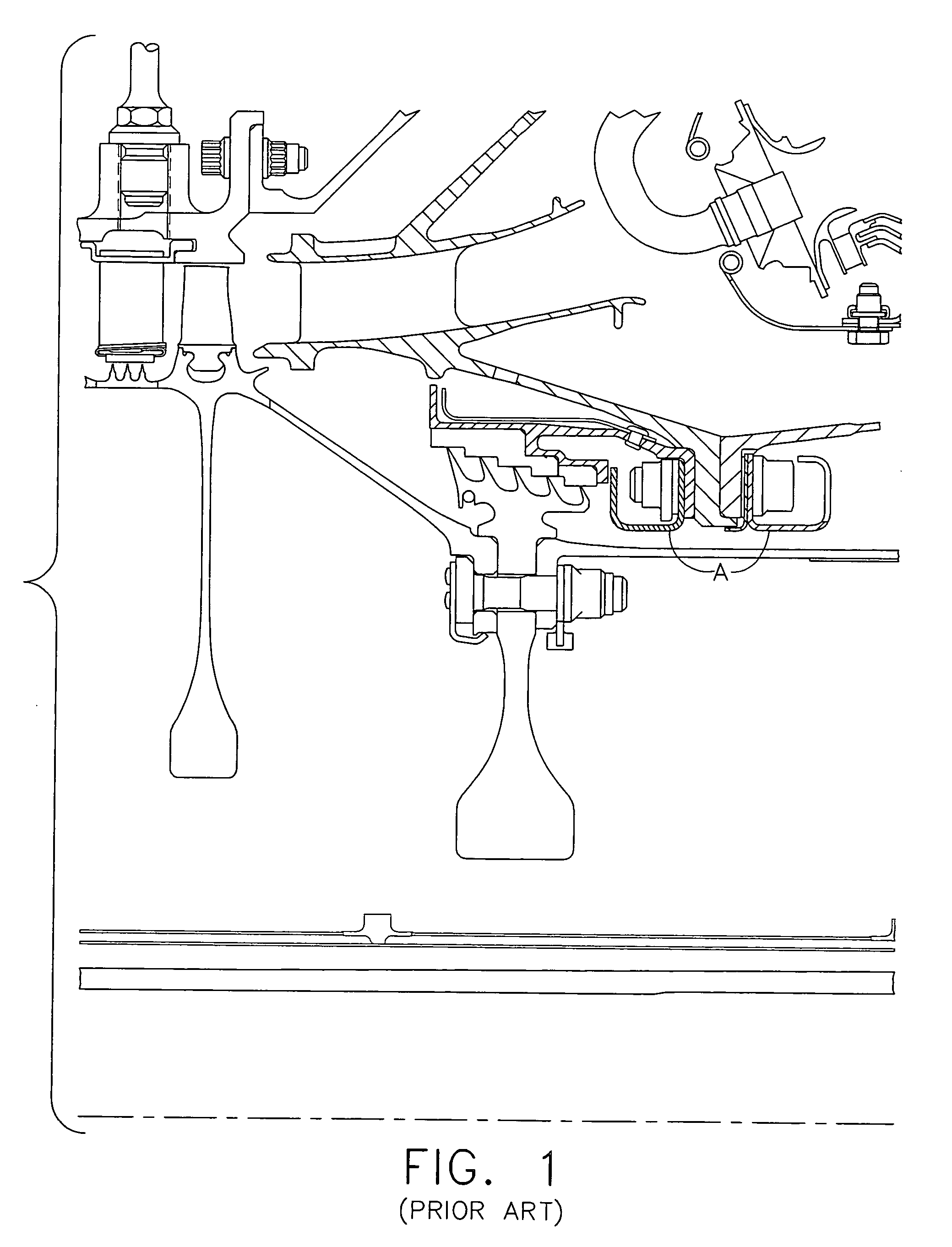
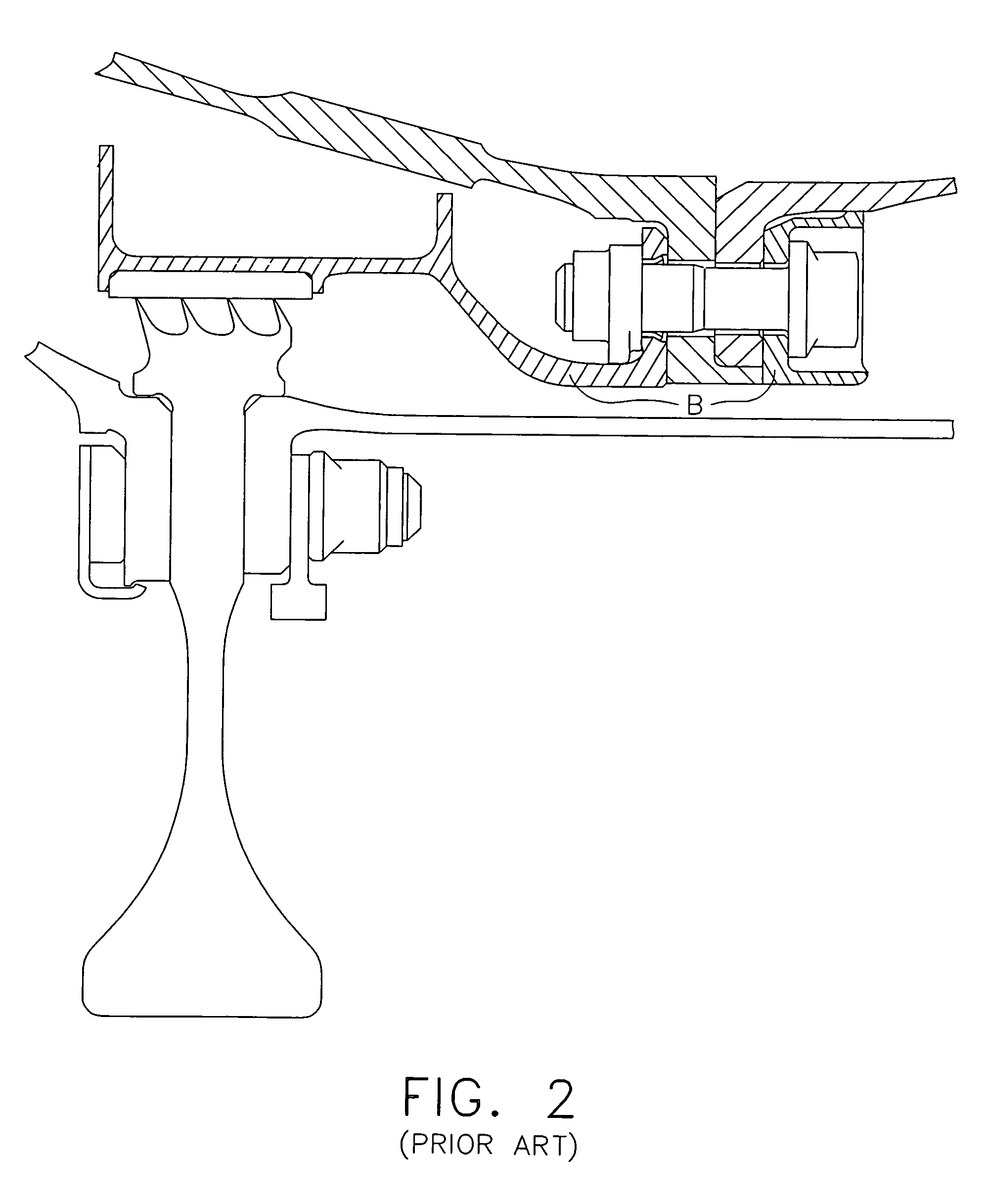
[0035]Referring now specifically to the drawings, prior art fastener shields are shown in FIGS. 1 and 2 at references A and B, respectively, as discussed above with reference to U.S. Pat. Nos. 4,190,397 and 5,090,865.

[0036]A gas turbine engine incorporating a fastener shield according to the present invention is illustrated in FIG. 3 and shown generally at reference numeral 10. The engine 10 includes an annular outer casing 12 that encloses the operating components of the engine 10. Engine 10 has a longitudinal axis 11, about which the several rotating components of the engine 10 rotate. An air inlet 14 is provided into which air is drawn. The air enters a fan section 16 containing a fan 17 within which the pressure and the velocity of the inlet air are increased. Fan section 16 includes a multiple-stage fan 17 that is enclosed by a fan casing 18.

[0037]Fan outlet air exits from the multiple-stage fan 17 and passes an annular divider 20 that divides the fan outlet air stream into a b...


PUM


Abstract

A fastener shield for use in a fluid flow path within a gas turbine engine for reducing fluid drag and heating generated by fluid flow over a plurality of circumferentially spaced bolts. The fastener shield has a radially-extending, downstream-facing mounting flange with a plurality of circumferentially spaced bolt holes positioned to receive respective engine mounting bolts therethrough and to attach the mounting flange to elements of the turbine engine. A curved, upstream-facing fastener shield cover is positioned in spaced-apart relation to the mounting flange for at least partially covering and separating an exposed, upstream-facing portion of the bolts from the fluid flow to thereby reduce drag and consequent heating of the bolts. A plurality of closely spaced-apart, spirally-oriented channels are formed in the fastener shield cover for deflecting the fluid flow impinging on the fastener shield cover, thereby increasing the tangential velocity and lowering the relative temperature of the fluid flow.

Description

TECHNICAL FIELD AND BACKGROUND OF THE INVENTION[0001]This invention relates generally to turbomachines such as gas turbine engines and, more particularly, to an improved fastener shield for minimizing temperature rise associated with protrusions in a fluid flow path.[0002]U.S. Pat. Nos. 4,190,397 and 5,090,865, assigned to the assignee of the present invention, each describe the need for and use of fastener shields, referred to therein as “windage shields”, in gas turbine engines. In particular, the efficiency of the engine is directly related to the ability of the engine to operate at higher turbine inlet temperatures. The need for higher turbine operating temperatures requires cooling air to be supplied to various components of the engine in order to allow the components to operate at the higher temperatures without being subjected to thermal stress to a degree that is damaging to the engine.[0003]In order to supply cooling air at a temperature that is effective to lower the tempe...

Claims


Application Information

Patent Timeline
Patent Type & Authority Patents(United States)
IPC IPC(8): F04D29/08
CPCF01D11/001F01D25/243F05D2260/97F05B2260/301
Inventor DONG, ZHIFENGEPSTEIN, MICHAEL J.ANDERSON, WILLIAM C.SENYO, JESSE
Owner GENERAL ELECTRIC CO
Why Eureka
Try Eureka