Capacitor-based powering system and associated methods

a powering system and capacitor technology, applied in the field of powering systems, can solve the problems of increased cranking power, increased cranking power, and more difficult engine start, and achieve the effects of enhancing the cranking power of the engine, facilitating manufacturing, and being easily integrated into the current design of the vehicl

Inactive Publication Date: 2006-08-22
SURE POWER INDS +1
View PDF38 Cites 9 Cited by
  • Summary
  • Abstract
  • Description
  • Claims
  • Application Information

AI Technical Summary

Benefits of technology

[0013]With the foregoing in mind, the present invention advantageously provides an engine ignition and powering system that provides increased power for cranking an internal combustion engine and powering auxiliary electrical devices in a vehicle. An additional advantage of the present invention is the system's enhanced reliability under all operating conditions. Still further advantage of the present invention is the ability to reliably maintain the system's capabilities over prolonged periods of use. Another distinct advantage of the present invention is that the system provides cranking power to the engine independently of whether or not power is available from a conventional battery; a conventional battery can be advantageously incorporated as part of the system, but is not essential for starting the engine.
[0014]Moreover, a further advantage of the present invention is that the system also can power auxiliary electrical devices in a vehicle regardless of whether or not power is available from a conventional battery. This advantage can be critical even with a vehicle powered by both a capacitor and battery. Virtually all modern vehicles rely on various ECUs, and these ECUs include ones essential for controlling the sequence and operation of devices used to start the vehicle. Thus, in a vehicle disabled by a discharged battery, it is necessary to power not only the motor of the starter but also ECUs associated with engine starting. The system, according to the present invention, provides this critical capability.
[0015]Among the other distinct advantages provided by the present invention are control mechanisms that are operably efficient and easy to manufacture, especially as compared to conventional systems currently available. Yet an additional advantage is that the system can easily be incorporated into currently designed vehicles. As described herein, below, the features of the system are particularly advantageous when incorporated in heavy-duty vehicles commonly employed for transportation, construction, and agriculture.
[0016]The present invention, more specifically, provides an enhanced-power, capacitor-based starting system. The system incorporates a specialized capacitor having additional cells (i.e., an auxiliary-celled capacitor) that provide enhanced cranking power to the engine. As explained more fully below, it is recognized by the present invention that the powering capability of the capacitor is a function of the number of cells and accordingly the number of cells is dictated by the size of the engine. Thus, according to the present invention, adjustment of number of the capacitor cells provides an efficient method of adapting a capacitor so as to function effectively when incorporated into a vehicle having any set of engine, starter, and alternator parameters.
[0017]The system controls energy exchanges among the capacitor, starter, and alternator such that the starter and solenoid coils are supplied with power solely by the capacitor during the starting cycle thereby ensuring that starts are fast and efficient. When the engine has been started and is running under its own power, the system directs power from the alternator to the capacitor so that the charge of the capacitor is reliably maintained under virtually any operating conditions. More specifically, the system automatically connects the capacitor and the alternator in response only to a signal supplied by the alternator in the form of electrical current generated only if the alternator is operatively functioning.
[0018]Preferably control is provided using a single switch—more preferably a magnetic switch (solenoid) or an electron field effect transistor (FET)—that isolates the capacitor from the battery and the rest of the electrical system of the vehicle when the alternator is not generating electrical current. The alternator current provides a signal to close the otherwise open switch and connect the alternator and the capacitor. Preferably, when the engine is running and the alternator is producing current, the alternator's “I” terminal signals the switch to close thereby permitting the current generated by the alternator to flow to the capacitor as well as the battery so that both are charged with the vehicle alternator.

Problems solved by technology

For example, during cold weather, the engine is more difficult to start thus requiring more energy to crank, and extra loads arise when devices such as the heater are left on while the engine is turned off.
A long-recognized limitation of lead storage batteries, however, is the batteries' inherent tendency toward relatively rapid depletion.
With continuous operation, moreover, the internal resistance of such a lead storage battery increases such that the battery's depletion occurs at an increasing rate over time.
A more fundamental limitation of Tsuchiya et al., however, is that the battery nevertheless remains essential because, it is the battery that maintains the charge of the capacitor.
A limitation noted in Tamor itself, however, is that the capacitor store relatively little energy and that capacitor recharging occur only infrequently.

Method used


Image

  • Capacitor-based powering system and associated methods
  • Capacitor-based powering system and associated methods
  • Capacitor-based powering system and associated methods

Examples


Embodiment Construction

[0034]The present invention will now be described more fully hereinafter with reference to the accompanying drawings which illustrate preferred embodiments of the invention. This invention may, however, be embodied in many different forms and should not be construed as limited to the embodiments set forth herein. Rather, these embodiments are provided so that this disclosure will be thorough and complete, and will fully convey the scope of the invention to those skilled in the art. Like numbers refer to like elements throughout, the prime notation, if used, indicates similar elements in alternative embodiments.

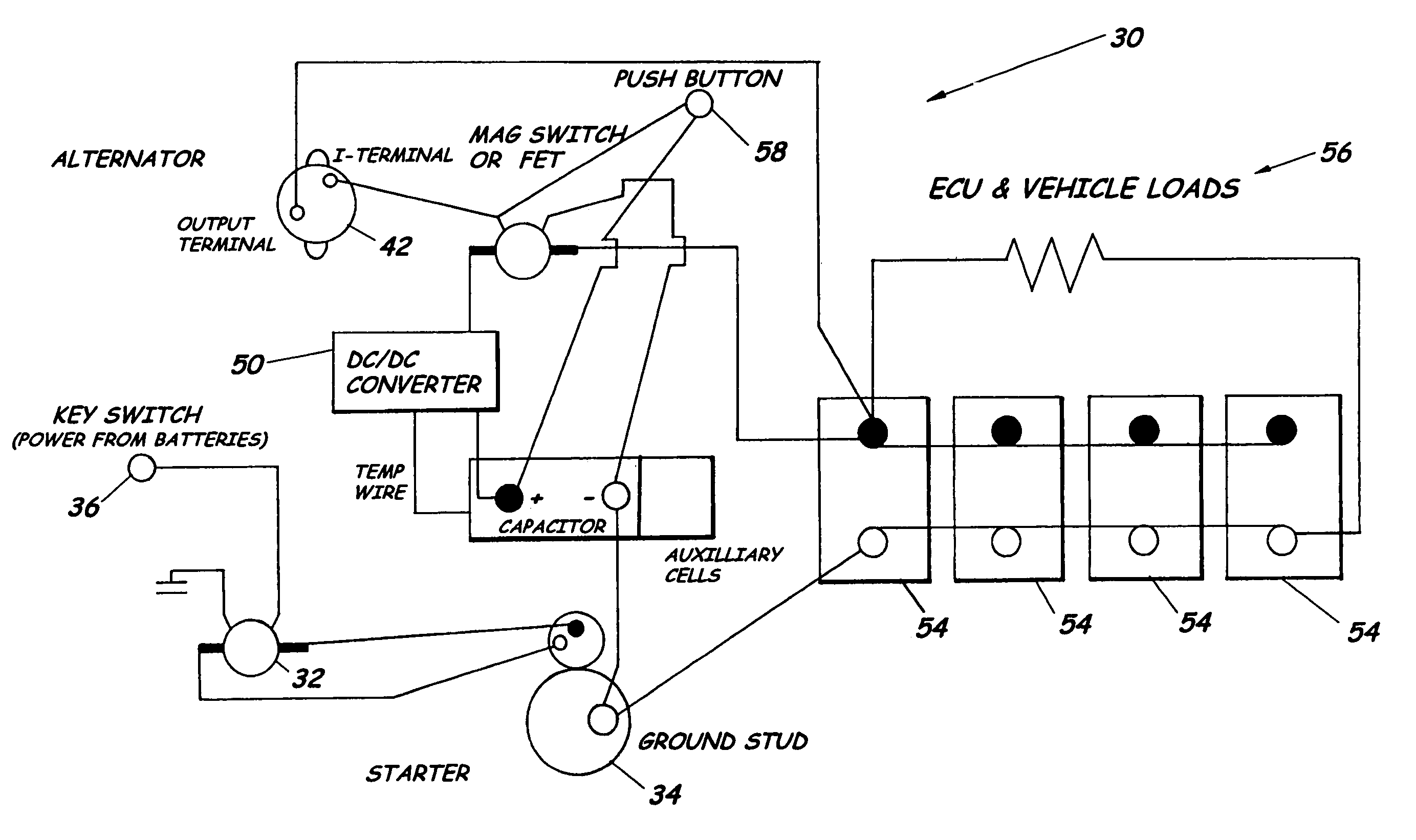
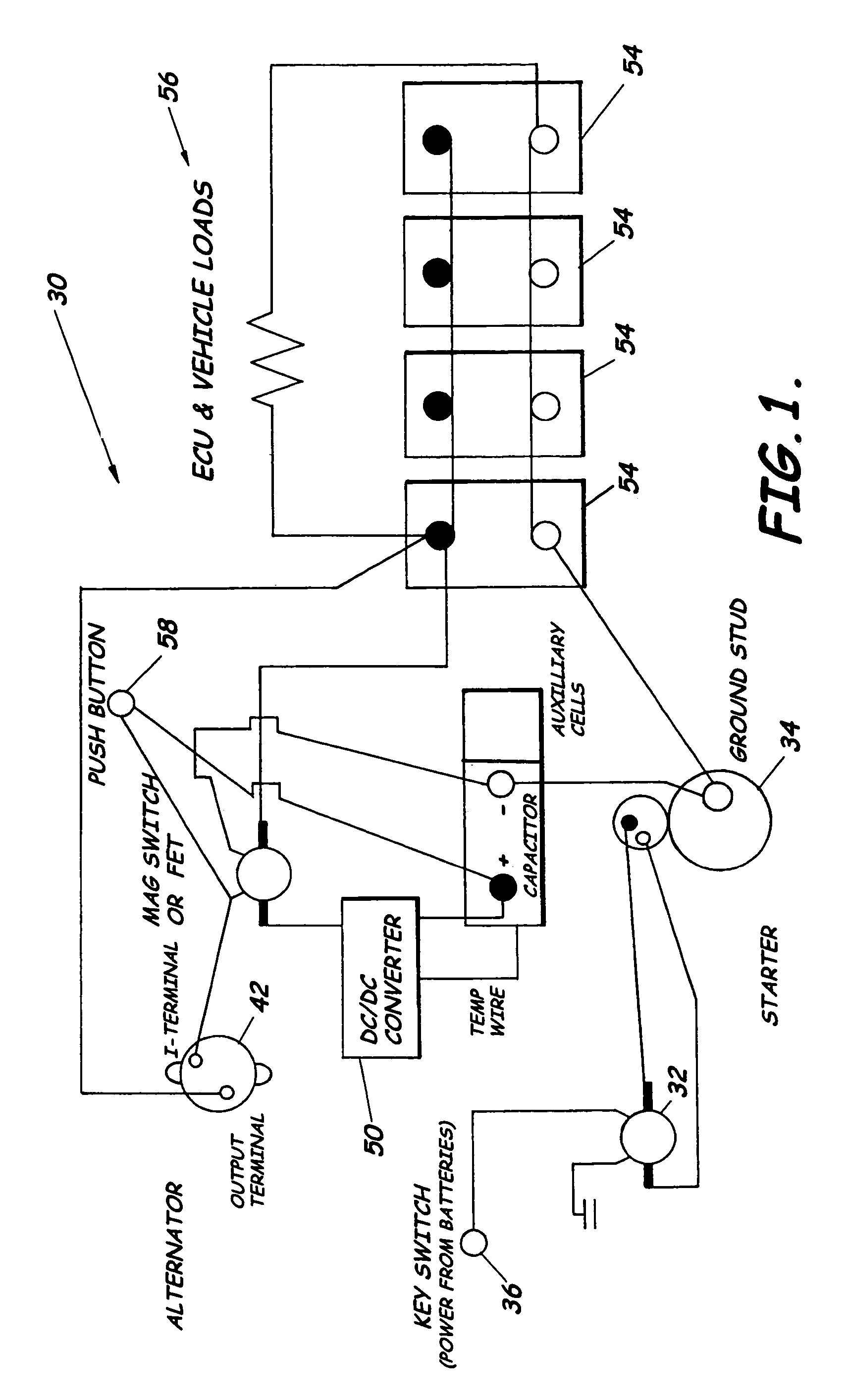
[0035]FIGS. 1–7 illustrate a capacitor-based power system 30 for starting an internal combustion engine 32 for use in any type of vehicle or equipment but providing particular advantage for powering heavy-duty vehicles and machinery requiring rapid starts under harsh operating conditions. As described below, the system 30 preferably includes a starter 34 powered by a special c...


PUM

PropertyMeasurementUnit
voltageaaaaaaaaaa
poweraaaaaaaaaa
voltageaaaaaaaaaa

Abstract

A system, capacitor having auxiliary cells, and associated methods for starting an engine is provided. The capacitor is an enhanced-power capacitor that provides enhanced cranking power. The capacitor is isolated from the battery and the rest of the engine's electrical system at preselected times. The capacitor is electrically connected to the alternator when the engine is running and is charged by the alternator. When the engine is not running, the capacitor is electrically isolated to prevent the capacitor discharging by powering accessory devices; the battery can power devices while the capacitor remains electrically isolated. During starting, the capacitor provides all the power supplied to the starter solenoid. If the battery is too weak to energize the electrical system during starting, an override allows the capacitor to provide power for all starting functions.

Description

CROSS REFERENCE TO RELATED APPLICATIONS[0001]This application is a continuation of U.S. patent application Ser. No. 09 / 938,796, filed on Aug. 24, 2001 now U.S. Pat No. 6,717,291.RELATED APPLICATIONS[0002]This application claims the benefit of and is related to Provisional Patent Application No. 60 / 286,772, filed Apr. 26, 2001 and titled Capacitor Starting System, Capacitor Having Auxiliary Cells, and Associated Methods, and Provisional Patent Application No. 60 / 238,903, filed Oct. 10, 2000 and titled Apparatus For Providing Portable Power To Machinery And Associated Methods, all of which are incorporated herein by reference in their entirety, and is a continuation-in-part of U.S. patent application Ser. No. 09 / 802,112, filed Mar. 8, 2001 now U.S. Pat. No. 6,426,606 and titled Apparatus For Providing Supplemental Power To An Electrical System and Related Methods.FIELD OF THE INVENTION[0003]The present invention relates to the field of powering systems and, more particularly, to capac...

Claims


Application Information

Patent Timeline
Patent Type & Authority Patents(United States)
IPC IPC(8): B60R22/00F02N11/14H01M6/50H01M10/42H01M10/46H01M50/202H01M50/204H01M50/249H02J7/00H02J7/34
CPCF02N11/14H01M2/1072H01M6/5033H02J7/0042H02J7/345H01M10/4264H02J2001/006H01M10/46H02J1/122Y02E60/10H01M50/204H01M50/249H01M50/202
Inventor PURKEY, BRUCESMITH, CARL
Owner SURE POWER INDS
Why Eureka
Try Eureka