Point diffraction interferometer with enhanced contrast

a point diffraction and contrast technology, applied in the field of interferometers, can solve the problems of deteriorating the accuracy of the wavefront measurement by this interferometer, and the inability to obtain sufficient contrast in the interference fringe, etc., and achieves the effects of improving the accuracy of the measurement of the wavefront, improving the accuracy of the measurement, and simple construction

Inactive Publication Date: 2006-08-22
PULSTEC IND
View PDF3 Cites 13 Cited by
  • Summary
  • Abstract
  • Description
  • Claims
  • Application Information

AI Technical Summary

Benefits of technology

[0007]The present invention is accomplished in view of the above-mentioned problem, and aims to provide an interferometer having improved an accuracy of a wavefront measurement by enhancing a contrast of interference fringes observed on an imaging device.

Problems solved by technology

As a result, a contrast of the interference fringes observed on the imaging device 17 is remarkably deteriorated, thereby deteriorating an accuracy of the wavefront measurement by this interferometer.
In case where a coherency of the light source is low such as a semiconductor laser, in particular, a sufficient contrast cannot be obtained in the interference fringes.

Method used


Image

  • Point diffraction interferometer with enhanced contrast
  • Point diffraction interferometer with enhanced contrast
  • Point diffraction interferometer with enhanced contrast

Examples


first embodiment

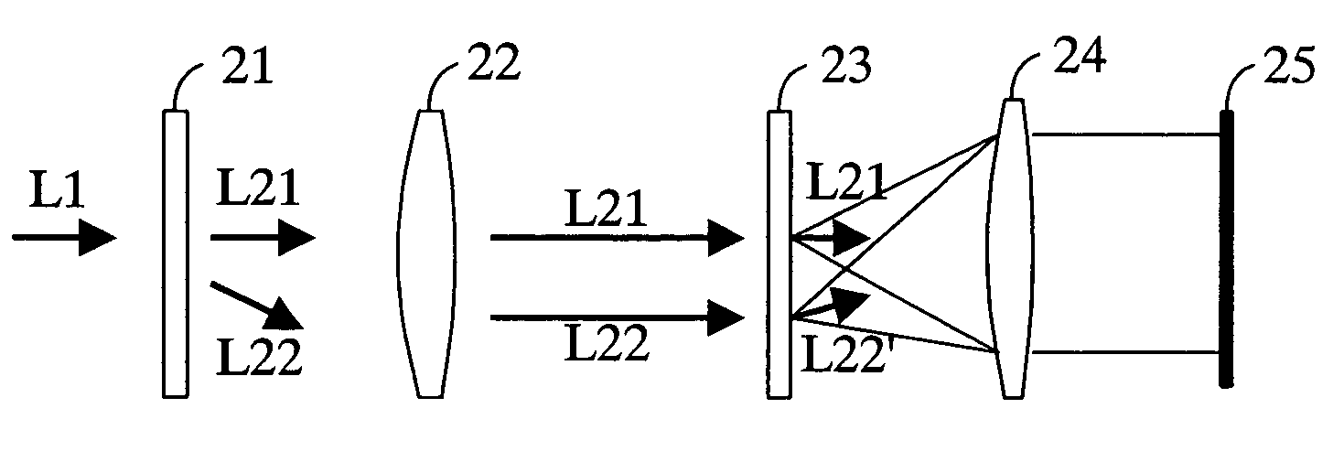
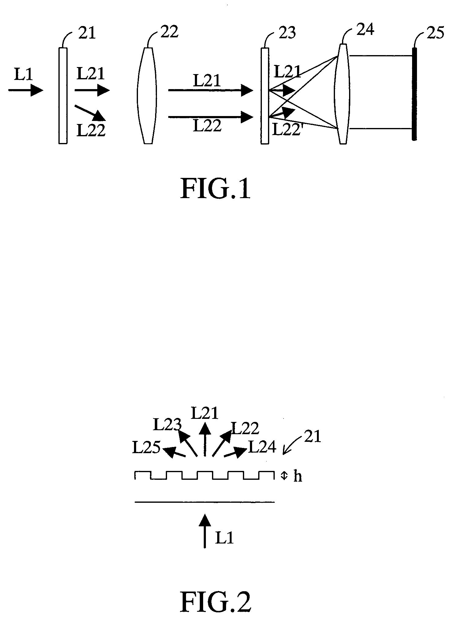
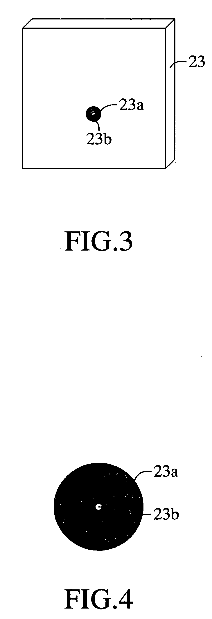
[0032]A first embodiment of the present invention will be explained herein below with reference to drawings. FIG. 1 schematically shows an interferometer according to the first embodiment for testing a performance of an incident beam L1. This interferometer has a diffraction grating 21 functioning as beam splitting means, a condenser lens 22 functioning as a first lens, a transparent substrate 23, a field lens 24 functioning as a second lens and an imaging device 25 arranged in this order.

[0033]The diffraction grating 21 has a cross section of a rectangular wave as shown in FIG. 2 that is a schematic sectional view. It produces a zeroth-order diffracted light L21, plus first-order diffracted light L22, minus first-order diffracted light L23, plus third-order diffracted light L24, minus third-order diffracted light L25 or the like with respect to the incident beam L1. It is to be noted that the diffracted lights used in this first embodiment are the zeroth-order diffracted light L21 ...

second embodiment

[0040]Subsequently, a second embodiment of the invention will be explained with reference to drawings. FIG. 5 schematically shows an interferometer according to the second embodiment for testing a performance of the incident beam L1. This interferometer is provided with a diffraction grating 31, beam splitter 32, mirror 33, lens 34 and imaging device 35.

[0041]The diffraction grating 31 has the same configuration as that of the diffraction grating 21 in the first embodiment and has the same function as that of the diffraction grating 21. It is to be noted that the diffracted lights used in this second embodiment too are the zeroth-order diffracted light L21 and the plus first-order diffracted light L22, so that the diffracted lights of the other order are unnecessary. Further, in this second embodiment too, only a part of the first-order diffracted light L22 reaches the imaging device 35 due to a transparent zone 33b of the mirror 33 described later, so that it is preferable to set t...

third embodiment

[0047]Subsequently, a third embodiment of the invention will be explained with reference to drawings. FIG. 8 schematically shows an interferometer according to the third embodiment. This interferometer utilizes a beam splitter 32A instead of the beam splitter 32. The beam splitter 32A transmits the zeroth-order diffracted light L21 and the plus first-order diffracted light L22 split by the diffraction grating 31 respectively to thereby allow these lights to reach the lens 34. And also, the beam splitter 32A reflects the zeroth-order diffracted light L21 and reference light L22′ propagated thereto from the lens 34 in the orthogonal direction to reach the imaging device 35. The other components are same as those in the second embodiment, so that they are given by the same numerals as in the second embodiment for omitting the explanation thereof.

[0048]In the third embodiment having the above-mentioned configuration too, the incident beam L1 that is a test subject is split into the zero...


PUM


Abstract

The interferometer has a diffraction grating 21, a condenser lens 22, a transparent substrate 23, a field lens 24 and an imaging device 25 arranged in this order. The transparent substrate 23 is arranged at the position in the optical axis direction where both focal spots of a zeroth-order diffracted light L21 and a first-order diffracted light L22 are formed. Formed on the transparent substrate 23 is a circular opaque zone 23a whose central position is the central position of the focal spot of the first-order diffracted light L22. Formed at the center of the opaque zone 23a is a pinhole 23b whose central position is the central position of the focal spot of the first-order diffracted light L22. The contrast of the interference fringes observed on the image device 25 is enhanced by the optical interference between the first-order diffracted light L22 passing through the pinhole 23b and the zeroth-order diffracted light L21 passing through the transparent substrate 23.

Description

BACKGROUND OF THE INVENTION[0001]1. Field of the Invention[0002]The present invention relates to an interferometer that is applied to test a performance of a beam itself emitted from various optical equipment or optical components or a performance of various optical equipment or optical components themselves, for measuring a wavefront of a beam.[0003]2. Description of the Prior Arts[0004]Conventionally, various types of interferometers have been well-known for measuring a wavefront of a beam, one of which is disclosed in a patent document (Japanese Unexamined Patent Application No. SHO57-64139). An interferometer disclosed in this patent document is provided with a light source 10, collimating lens 11, test lens 12 that is a subject to be tested and semi-transparent substrate 13 as shown in FIG. 13, wherein divergent light emitted from the light source 10 is converted into parallel beam by the collimating lens 11 and the converted parallel beam is focused on the semi-transparent sub...

Claims


Application Information

Patent Timeline
Patent Type & Authority Patents(United States)
IPC IPC(8): G01B9/02G01J9/02G01M11/02
CPCG01J9/02
Inventor FUKUI, KENJI
Owner PULSTEC IND
Why Eureka
Try Eureka