
Method and apparatus for dynamic biasing of baseband circuitry in a communication system receiver

a communication system and circuitry technology, applied in low-noise amplifiers, digital transmission, substation equipment, etc., can solve the problems of circuitry consuming an unduly high amount of power, certain amount of power consumption, and power consumption of the receiver baseband circuitry, so as to improve the control of baseband circuitry bias and reduce power consumption in the communication system

Active Publication Date: 2006-08-22
CIENA +1
View PDF13 Cites 39 Cited by
  • Summary
  • Abstract
  • Description
  • Claims
  • Application Information

AI Technical Summary

Benefits of technology

[0011]Advantageously, by providing improved control of baseband circuitry bias based on gain control information, the invention can significantly reduce power consumption in a communication system receiver.

Problems solved by technology

A drawback of existing communication system receivers is the amount of power consumed by the receiver baseband circuitry.
In a typical receiver, amplifiers in the baseband circuitry are biased at a substantially constant level, resulting in a certain amount of power consumption.
Information that may be known regarding signal strength is generally not utilized to adjust the bias level in the baseband circuitry, with the result that this circuitry may consume an unduly high amount of power under certain operating conditions.

Method used


Image

  • Method and apparatus for dynamic biasing of baseband circuitry in a communication system receiver
  • Method and apparatus for dynamic biasing of baseband circuitry in a communication system receiver
  • Method and apparatus for dynamic biasing of baseband circuitry in a communication system receiver

Examples


Embodiment Construction

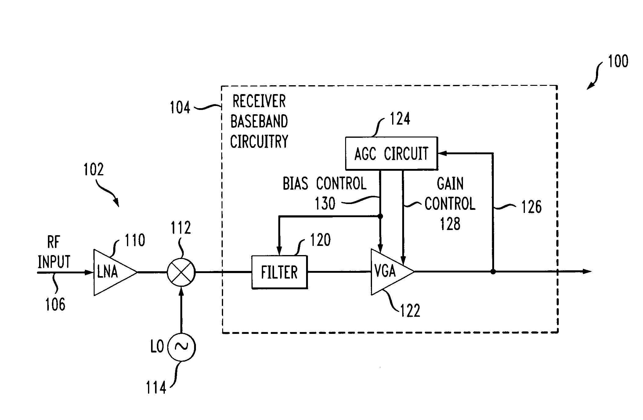
[0017]The present invention will be illustrated herein in an example receiver having a particular configuration of receiver baseband circuitry. It is to be appreciated, however, that the invention does not require the particular receiver and baseband circuitry configurations of the illustrative embodiments. The invention is more generally suitable for use in any communication receiver application in which it is desirable to provide improved power consumption through dynamic biasing of baseband circuitry. More particularly, the invention can be adapted for utilization in a wide variety of communication system receivers, including, for example, receivers associated with wireless networks such as IEEE 802.11 networks, digital audio broadcasting (DAB) systems, wireline systems such as digital subscriber line (DSL) systems, optical communication systems, etc. The term “receiver” as used herein is intended to encompass these and other communication system receivers. Moreover, the present ...


PUM


Abstract

Baseband receiver circuitry is dynamically biased in a communication system receiver by generating gain control information, and controlling an adjustable bias of at least a portion of the baseband circuitry based at least in part on the gain control information. The baseband receiver circuitry comprises at least one amplifier having an adjustable bias associated therewith, with the adjustable bias of the amplifier being controllable utilizing a bias control signal. For example, the amplifier may be an operational amplifier having a gain stage and an output buffer stage, with the bias control signal being applied to the output buffer stage to control an adjustable bias current thereof. More specifically, the bias control signal may be used to control an amount of current provided by at least one of a plurality of current sources associated with the output buffer stage of the amplifier, for example, by controlling a switch which enables or disables one or more of the current sources. Advantageously, the dynamic bias control can substantially reduce power consumption in the receiver. The techniques of the invention can also be applied to other types of devices which utilize gain control.

Description

FIELD OF THE INVENTION[0001]The present invention relates generally to communication system receivers or other devices utilizing gain control, and more particularly to biasing techniques for use in baseband amplifiers or other circuitry in a communication system receiver or other device.BACKGROUND OF THE INVENTION[0002]Communication system receivers commonly utilize automatic gain control (AGC) techniques to control gain in one or more receiver stages. For example, a typical receiver includes front end circuitry and baseband circuitry, each of which may have one or more separate AGC circuits associated therewith. Such AGC circuits are commonly utilized to adjust the gain of one or more amplifiers in a given signal path so as to maintain desired signal level ranges for the path in the presence of variations in received signal strength.[0003]An example of a known AGC circuit is described in U.S. Pat. No. 6,181,201, issued Jan. 30, 2001 to Peter J. Black and entitled “Automatic Gain Co...

Claims


Application Information

Patent Timeline
IPC IPC(8): H04B1/06H03F3/04H04L27/08
CPCH03F1/0272H03F3/50H03F2200/372H03F2200/294
Inventor AYTUR, TURGUT SEFKETBELK, NATHAN R.
Owner CIENA
Learn More